Introduction to IC Problem Identification
Integrated circuits (ICs) are essential components in modern electronic devices, ranging from smartphones and computers to industrial machinery and medical equipment. However, like any other electronic component, ICs can experience problems that affect the overall performance and reliability of the device. Identifying IC problems is crucial for troubleshooting, repairing, and maintaining electronic systems. In this article, we will explore various methods and techniques for identifying IC problems, helping you diagnose and resolve issues efficiently.
Common IC Problems
Before diving into the identification process, let’s discuss some common IC problems that you may encounter:
1. Open Circuits
An open circuit occurs when there is a break in the electrical path within the IC, preventing current from flowing through the affected pin or internal component. This can be caused by manufacturing defects, physical damage, or excessive stress on the IC.
2. Short Circuits
A short circuit happens when two or more pins or internal components of an IC are unintentionally connected, allowing current to flow through an unintended path. Short circuits can be caused by manufacturing defects, electrostatic discharge (ESD), or physical damage to the IC.
3. Parametric Failures
Parametric failures occur when an IC’s electrical characteristics, such as voltage, current, or timing, fall outside the specified range. These failures can be caused by manufacturing variations, environmental factors, or aging of the IC.
4. Functional Failures
Functional failures happen when an IC does not perform its intended function, even though its electrical characteristics may be within the specified range. These failures can be caused by design errors, manufacturing defects, or incompatibility with other components in the system.

Visual Inspection Techniques
Visual inspection is the first step in identifying IC problems. By examining the IC and its surrounding components, you can often spot signs of damage or abnormalities that may indicate a problem.
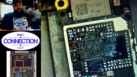
1. Inspection under Magnification
Using a magnifying glass or a microscope, carefully examine the IC for any visible signs of damage, such as:
- Cracks or chips in the IC package
- Bent or broken pins
- Discoloration or charring of the IC surface
- Foreign material or debris on the IC or its pins
2. Inspection of Solder Joints
Check the solder joints that connect the IC to the printed circuit board (PCB). Look for any signs of poor soldering, such as:
- Cold solder joints (dull, grainy appearance)
- Excessive or insufficient solder
- Solder bridges between pins
- Lifted or misaligned IC pins
3. Thermal Imaging
Thermal imaging cameras can help identify ICs that are generating excessive heat, which may indicate a problem. Look for hot spots on the IC or surrounding components that deviate significantly from the normal thermal profile of the system.

Electrical Testing Methods
Electrical testing involves measuring the IC’s electrical characteristics and comparing them to the expected values specified in the datasheet. This helps identify parametric and functional failures.
1. Continuity Testing
Use a multimeter to test the continuity between the IC’s pins and the PCB traces. This helps identify open circuits and ensures proper connections between the IC and other components.
2. Voltage and Current Measurements
Measure the voltage and current at the IC’s pins and compare them to the expected values. Pay attention to the supply voltage, input/output voltages, and current consumption. Deviations from the specified ranges may indicate a problem with the IC or the surrounding circuitry.
3. Oscilloscope Measurements
An oscilloscope allows you to visualize and analyze the waveforms at the IC’s pins. This is particularly useful for identifying timing-related issues, such as:
- Signal integrity problems (e.g., ringing, overshoot, undershoot)
- Incorrect timing or frequency of clock signals
- Abnormal waveform shapes or amplitudes
4. In-Circuit Testing
In-circuit testing involves using a specialized test fixture or probe to access the IC’s pins while it is still soldered to the PCB. This allows you to perform more comprehensive tests, such as:
- Functional testing of the IC’s inputs and outputs
- Boundary scan testing (for ICs with built-in test features)
- Parametric testing of the IC’s electrical characteristics

Comparison with Known Good Circuit
Comparing the suspect IC’s behavior and electrical characteristics with a known good circuit can help identify problems. This technique is particularly useful when you have access to a functioning system that uses the same type of IC.
1. Side-by-Side Comparison
Set up the suspect and known good systems side by side and compare their behavior. Look for any differences in functionality, performance, or error messages.
2. Waveform Comparison
Using an oscilloscope, capture the waveforms at the IC’s pins on both the suspect and known good systems. Compare the waveforms for any discrepancies in shape, amplitude, or timing.
3. Voltage and Current Comparison
Measure the voltage and current at the IC’s pins on both systems and compare the values. Any significant differences may indicate a problem with the suspect IC or its surrounding circuitry.
Failure Analysis Techniques
When visual inspection and electrical testing do not provide conclusive results, more advanced failure analysis techniques may be necessary. These techniques typically require specialized equipment and expertise.
1. X-Ray Imaging
X-ray imaging allows you to see inside the IC package without physically opening it. This technique can reveal internal defects, such as:
- Cracks in the die or substrate
- Voids or delamination in the die attach or wire bonds
- Foreign material or debris inside the package
2. Decapsulation
Decapsulation involves removing the IC package to expose the die and internal components. This allows for direct visual inspection and probing of the die. However, decapsulation is a destructive process and should only be performed when other methods have been exhausted.
3. Scanning Electron Microscopy (SEM)
SEM provides high-resolution images of the IC’s surface and internal structures. This technique can reveal microscopic defects, such as:
- Cracks or voids in the metal layers
- Electromigration or corrosion of the interconnects
- Gate oxide damage or breakdown
4. Focused Ion Beam (FIB)
FIB allows for precise milling and imaging of the IC’s internal structures. This technique can be used to:
- Cross-section specific areas of the die for analysis
- Modify or repair the IC’s internal connections
- Extract samples for further analysis (e.g., transmission electron microscopy)
Frequently Asked Questions (FAQ)
1. What are the most common causes of IC failures?
The most common causes of IC failures include:
- Electrostatic discharge (ESD)
- Overheating or thermal stress
- Physical damage (e.g., mechanical shock, vibration)
- Manufacturing defects
- Aging or wear-out of the IC
2. Can all IC problems be identified through visual inspection?
No, not all IC problems can be identified through visual inspection alone. Some issues, such as parametric failures or internal defects, may require electrical testing or advanced failure analysis techniques to detect.
3. What safety precautions should I take when handling ICs?
When handling ICs, always take the following safety precautions:
- Use ESD protection (e.g., grounded wrist strap, ESD-safe work surface)
- Handle ICs by their edges or packaging, avoiding contact with the pins
- Avoid exposing ICs to extreme temperatures, humidity, or mechanical stress
- Follow proper storage and handling procedures as specified by the manufacturer
4. Can I replace a faulty IC with a different part number?
In general, it is not recommended to replace a faulty IC with a different part number unless the replacement is specified as a compatible substitute by the manufacturer. Different part numbers may have variations in electrical characteristics, pinout, or functionality that could affect the system’s performance.
5. When should I seek professional help for identifying IC problems?
If you have exhausted all available troubleshooting methods and are still unable to identify the IC problem, or if the issue requires specialized equipment or expertise, it is advisable to seek professional help from an experienced electronIC repair service or the IC manufacturer’s support team.
Conclusion
Identifying IC problems is a critical skill for anyone involved in the design, maintenance, or repair of electronic systems. By combining visual inspection, electrical testing, and advanced failure analysis techniques, you can effectively diagnose and resolve IC issues. Remember to approach the problem systematically, starting with non-destructive methods and progressively moving towards more invasive techniques as needed. With practice and experience, you will develop a keen eye for spotting IC problems and efficiently troubleshooting electronic systems.
