Judy@4pcba.com
7:30 AM - 7:30 PM
Monday to Saturday

Category: PCB REVERSE ENGINEERING & IC CRACK

How to solve the problem of QFP solder bridging

What is QFP solder bridging?

QFP (Quad Flat Package) is a surface-mount integrated circuit package with leads extending from each of the four sides. QFP packages are commonly used for microcontrollers, microprocessors, and other complex ICs.

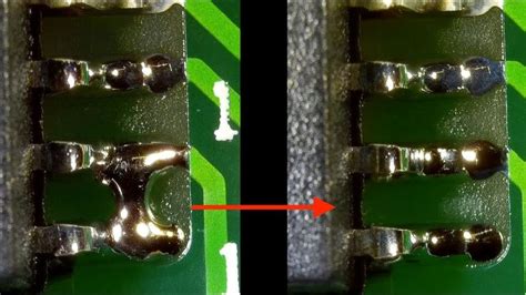
Solder bridging is a defect that occurs when solder inadvertently connects adjacent pins or pads, creating an unintended short circuit. QFP packages are particularly prone to solder bridging due to the fine pitch (small spacing) between the leads.

Solder bridging can cause various issues, such as:
– Malfunctioning or non-functioning devices
– Intermittent problems that are difficult to diagnose
– Reduced reliability and product lifespan
– Increased manufacturing costs due to rework or scrap

Causes of QFP Solder Bridging

Several factors can contribute to the occurrence of solder bridging in QFP packages:

1. Inadequate Solder Paste Printing

Inconsistent or excessive solder paste application can lead to solder bridging. This can be caused by:
– Worn or damaged stencils
– Improper stencil thickness
– Incorrect stencil aperture size or shape
– Poor stencil alignment
– Inadequate stencil cleaning

2. Improper Reflow Profile

An incorrect reflow profile can cause solder bridging by:
– Insufficient preheating, leading to cold solder joints
– Excessive peak temperature, causing solder splatter
– Inadequate cooling rate, allowing solder to flow between leads

3. Component Placement Issues

Inaccurate component placement can result in solder bridging, especially if the leads are not properly aligned with the pads. Common causes include:
– Poor pick-and-place machine calibration
– Incorrect component orientation
– Bent or misaligned leads

4. PCB Design Flaws

PCB design issues can contribute to solder bridging, such as:
– Insufficient pad-to-pad spacing
– Inadequate solder mask clearance
– Incorrect pad size or shape

5. Environmental Factors

Environmental conditions can also impact solder bridging, including:
– High humidity, which can cause solder paste slumping
– Dust or debris contamination
– Electrostatic discharge (ESD) events

Preventing QFP Solder Bridging

To minimize the occurrence of QFP solder bridging, consider the following preventive measures:

1. Optimize Solder Paste Printing

Ensure consistent and accurate solder paste application by:
– Using high-quality, well-maintained stencils
– Selecting the appropriate stencil thickness and aperture size
– Implementing proper stencil alignment and cleaning procedures
– Regularly inspecting and replacing worn or damaged stencils

2. Fine-tune Reflow Profile

Develop and optimize the reflow profile for each specific PCB Assembly by:
– Conducting thermal profiling to ensure proper preheating, peak temperature, and cooling rates
– Adjusting the reflow profile based on the solder paste manufacturer’s recommendations
– Monitoring and controlling oven temperature and conveyor speed

3. Improve Component Placement Accuracy

Ensure precise component placement by:
– Regularly calibrating and maintaining pick-and-place machines
– Using vision systems to verify component orientation and alignment
– Inspecting components for bent or misaligned leads prior to placement

4. Optimize PCB Design

Design PCBs with solder bridging prevention in mind by:
– Providing adequate pad-to-pad spacing, especially for fine-pitch QFP packages
– Ensuring proper solder mask clearance around pads
– Optimizing pad size and shape for improved solder joint formation

5. Control Environmental Conditions

Maintain a clean and controlled manufacturing environment by:
– Regulating humidity levels to prevent solder paste slumping
– Implementing strict cleanliness protocols to minimize dust and debris
– Utilizing ESD Protection measures to prevent electrostatic discharge events

Detecting and Reworking QFP Solder Bridges

Despite preventive measures, solder bridging may still occur. Early detection and proper rework techniques are crucial for minimizing the impact on product quality and manufacturing costs.

1. Visual Inspection

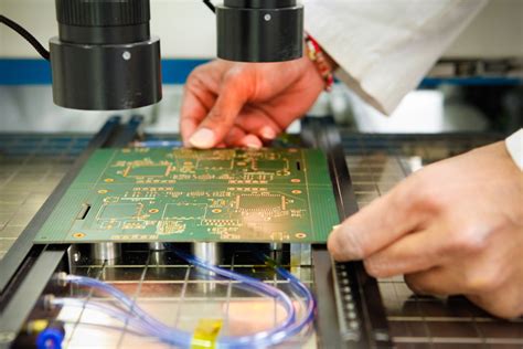
Visual inspection is the most common method for detecting solder bridges. This can be done using:
– Magnifying lenses or microscopes
– Automated optical inspection (AOI) systems
– X-ray inspection for hidden solder bridges

When visually inspecting QFP packages for solder bridges, pay close attention to:
– Adjacent leads or pads that appear to be connected by solder
– Solder that extends beyond the pad edges
– Irregular or excessive solder joint shapes

2. Electrical Testing

Electrical testing can help identify solder bridges that may not be visible during visual inspection. Common electrical testing methods include:
– In-circuit testing (ICT)
Flying Probe testing
– Boundary scan testing

These methods can detect short circuits caused by solder bridges and help pinpoint the affected leads or pads.

3. Rework Techniques

When a solder bridge is detected, it must be carefully removed to restore proper functionality. Common rework techniques for QFP packages include:

Manual Soldering

For small-scale rework, manual soldering can be used to remove solder bridges. This involves:
1. Applying flux to the affected area to help remove the excess solder
2. Using a fine-tipped soldering iron to carefully remove the solder bridge
3. Cleaning the area with isopropyl alcohol to remove flux residue

Hot Air Rework

Hot air rework is a more advanced technique that involves:
1. Applying flux to the affected area
2. Using a focused hot air nozzle to melt the solder bridge
3. Removing the excess solder using a vacuum pickup tool or solder wick
4. Cleaning the area with isopropyl alcohol

Solder Wick

Solder wick, also known as desoldering braid, can be used to remove solder bridges by:
1. Placing the solder wick over the solder bridge
2. Applying heat to the wick using a soldering iron, causing the excess solder to be absorbed into the wick
3. Removing the wick and cleaning the area with isopropyl alcohol

When performing rework on QFP packages, take care to:
– Avoid applying excessive heat, which can damage the component or PCB
– Use the appropriate tools and materials for the specific package and solder type
– Verify that the solder bridge has been completely removed and that no new bridges have been created during the rework process

Best Practices for QFP Solder Bridging Prevention and Rework

To effectively prevent and address QFP solder bridging, consider adopting the following best practices:

1. Establish and Maintain Process Controls

Implement and regularly review process controls for:
– Solder paste printing
– Reflow soldering
– Component placement
– PCB design
– Environmental conditions

Document and communicate these controls to all relevant personnel, and ensure that they are consistently followed.

2. Provide Regular Training

Train personnel on:
– The causes and effects of QFP solder bridging
– Preventive measures and best practices
– Detection and rework techniques

Regular training helps maintain a high level of awareness and expertise among the workforce.

3. Implement Quality Control Measures

Establish quality control measures throughout the manufacturing process, including:
– Incoming inspection of components and materials
– Solder paste inspection (SPI) after printing
– Automated optical inspection (AOI) after component placement and reflow
– X-ray inspection for hidden solder bridges
– Electrical testing to verify functionality

These measures help detect issues early in the process, reducing the need for costly rework or scrap.

4. Foster Continuous Improvement

Encourage a culture of continuous improvement by:
– Regularly reviewing and analyzing process data and quality metrics
– Identifying root causes of solder bridging issues
– Implementing corrective and preventive actions (CAPAs)
– Sharing knowledge and best practices across teams and departments

Continuously improving processes and practices helps reduce the occurrence of QFP solder bridging over time.

5. Collaborate with Suppliers and Industry Experts

Work closely with suppliers and industry experts to:
– Stay informed about the latest technologies, materials, and processes
– Troubleshoot complex solder bridging issues
– Identify opportunities for process optimization and improvement

Collaborating with external partners can provide valuable insights and expertise to help address QFP solder bridging challenges.

By implementing these best practices and continuously refining processes, manufacturers can effectively prevent and address QFP solder bridging, improving product quality, reliability, and overall manufacturing efficiency.

Frequently Asked Questions (FAQ)

1. What is the main cause of QFP solder bridging?

The main cause of QFP solder bridging is the fine pitch (small spacing) between the leads, which makes it easier for solder to inadvertently connect adjacent pins or pads. However, various factors can contribute to the occurrence of solder bridging, including inadequate solder paste printing, improper reflow profile, component placement issues, PCB design flaws, and environmental factors.

2. How can I prevent QFP solder bridging in my assembly process?

To prevent QFP solder bridging, you should focus on optimizing various aspects of your assembly process, such as:
– Ensuring consistent and accurate solder paste printing
– Fine-tuning the reflow profile for your specific PCB assembly
– Improving component placement accuracy
– Optimizing PCB design for solder bridging prevention
– Controlling environmental conditions, such as humidity and cleanliness

3. What are the most common methods for detecting QFP solder bridges?

The most common methods for detecting QFP solder bridges are:
– Visual inspection using magnifying lenses, microscopes, or automated optical inspection (AOI) systems
– X-ray inspection for hidden solder bridges
– Electrical testing methods, such as in-circuit testing (ICT), flying probe testing, and boundary scan testing

4. How can I safely remove a QFP solder bridge without damaging the component or PCB?

To safely remove a QFP solder bridge, you can use one of the following rework techniques:
– Manual soldering using a fine-tipped soldering iron and flux
– Hot air rework using a focused hot air nozzle and vacuum pickup tool
– Solder wick (desoldering braid) to absorb the excess solder

When performing rework, be sure to use the appropriate tools and materials, avoid applying excessive heat, and thoroughly clean the area after removing the solder bridge.

5. What are some best practices for addressing QFP solder bridging in a manufacturing environment?

To effectively address QFP solder bridging in a manufacturing environment, consider adopting the following best practices:
– Establish and maintain process controls for all relevant aspects of the assembly process
– Provide regular training to personnel on solder bridging prevention and rework techniques
– Implement quality control measures throughout the manufacturing process
– Foster a culture of continuous improvement by regularly reviewing data, identifying root causes, and implementing corrective actions
– Collaborate with suppliers and industry experts to stay informed and optimize processes

By implementing these best practices, manufacturers can systematically prevent and address QFP solder bridging issues, leading to improved product quality and overall manufacturing efficiency.
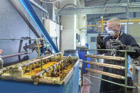
Electronics Manufacturing

Introduction to Electro-Manufacturing

Electro-manufacturing, also known as electronics manufacturing, is the process of designing, fabricating, assembling, and testing electronic components, devices, and systems. This industry plays a crucial role in the modern world, as electronic products are ubiquitous in our daily lives, from smartphones and computers to automotive systems and medical devices. The electronics manufacturing sector is constantly evolving, driven by rapid technological advancements, changing consumer demands, and the need for cost-effective and efficient production processes.

Key Components of Electro-Manufacturing

  1. Electronic Components: The building blocks of electronic devices, including resistors, capacitors, inductors, transistors, and integrated circuits (ICs).
  2. Printed Circuit Boards (PCBs): The foundation upon which electronic components are mounted and interconnected to form a functional circuit.
  3. Assembly Processes: The methods used to place and connect electronic components on PCBs, such as surface mount technology (SMT) and through-hole technology (THT).
  4. Testing and Quality Control: The procedures employed to ensure that electronic products meet specified performance, reliability, and safety standards.

The Electro-Manufacturing Process

1. Product Design and Development

The electro-manufacturing process begins with the design and development of an electronic product. This stage involves several key steps:

a. Concept Generation

  • Identifying market needs and opportunities
  • Brainstorming and ideation
  • Feasibility assessment

b. Schematic Design

  • Creating a schematic diagram that represents the electrical connections and components of the product
  • Selecting appropriate components based on functionality, cost, and availability
  • Simulating and validating the schematic design using electronic design automation (EDA) tools

c. PCB Layout Design

  • Translating the schematic into a physical PCB layout
  • Determining the optimal placement of components and routing of traces
  • Ensuring proper signal integrity, power distribution, and thermal management
  • Adhering to design for manufacturability (DFM) guidelines

d. Prototyping and Testing

  • Fabricating prototype PCBs and assembling the components
  • Conducting functional and performance tests to validate the design
  • Making necessary revisions and optimizations based on test results

2. PCB Fabrication

Once the PCB layout design is finalized, the next step is to manufacture the physical PCBs. This process involves several stages:

a. PCB Material Selection

  • Choosing the appropriate substrate material based on the product’s requirements (e.g., FR-4, high-frequency laminates, flexible substrates)
  • Selecting the copper foil thickness and the number of layers needed

b. PCB Imaging

  • Creating a photomask or stencil based on the PCB layout design
  • Applying a photoresist layer on the copper-clad substrate
  • Exposing the photoresist to UV light through the photomask, hardening the exposed areas

c. Etching and Plating

  • Removing the unexposed photoresist and etching away the unwanted copper, leaving behind the desired circuit pattern
  • Plating the exposed copper traces with a protective finish (e.g., solder mask, silkscreen)
  • Applying surface finishes (e.g., HASL, ENIG, OSP) to the exposed pads and vias

d. Drilling and Routing

  • Drilling holes for through-hole components and vias
  • Routing the PCB outline and any required cutouts or slots

3. PCB Assembly

With the fabricated PCBs ready, the next stage is to assemble the electronic components onto the boards. This process can be carried out using various methods, depending on the type of components and the production volume.

a. Surface Mount Technology (SMT)

  • Applying solder paste to the PCB pads using a stencil or screen printing
  • Placing surface mount components onto the solder paste using pick-and-place machines
  • Reflowing the solder paste in a controlled oven to form permanent solder joints

b. Through-Hole Technology (THT)

  • Inserting through-hole components into the drilled holes on the PCB
  • Soldering the component leads to the PCB pads using wave soldering or manual soldering techniques

c. Inspection and Rework

  • Visually inspecting the assembLED PCBs for defects, such as incorrect component placement, solder bridges, or poor solder joints
  • Using automated optical inspection (AOI) systems for high-volume production
  • Performing necessary rework and repairs on defective assemblies

4. Testing and Quality Control

To ensure that the assembled electronic products meet the required performance and reliability standards, various testing and quality control procedures are employed.

a. In-Circuit Testing (ICT)

  • Testing individual components and their interconnections on the PCB using a bed-of-nails fixture
  • Identifying and isolating faulty components or connections

b. Functional Testing

  • Verifying that the assembled product functions as intended under normal operating conditions
  • Conducting tests such as power-on self-test (POST), boundary scan, and system-level functional tests

c. Environmental Testing

  • Subjecting the product to various environmental stresses, such as temperature cycling, humidity, vibration, and shock
  • Ensuring that the product can withstand the expected operating conditions and have an acceptable lifespan

d. Burn-In Testing

  • Running the product under elevated temperature and voltage conditions for an extended period
  • Identifying early failures and weeding out potential defects before the product is shipped

5. Packaging and Shipping

Once the electronic products have passed all the necessary tests and quality checks, they are ready for packaging and shipping to the end customers or distributors.

a. Packaging Design

  • Developing appropriate packaging materials and designs to protect the products during transportation and storage
  • Considering factors such as electrostatic discharge (ESD) protection, moisture barrier, and shock absorption

b. Labeling and Documentation

  • Applying necessary labels, barcodes, and markings on the product and packaging for identification and traceability
  • Including required documentation, such as user manuals, warranty information, and compliance certificates

c. Inventory Management and Logistics

  • Managing inventory levels and ensuring timely delivery of products to customers
  • Coordinating with logistics partners for efficient transportation and distribution

Advancements in Electro-Manufacturing

The electronics manufacturing industry is constantly evolving, driven by technological advancements and changing market demands. Some of the key trends and developments in electro-manufacturing include:

1. Miniaturization and High-Density Packaging

  • The trend towards smaller, more compact electronic devices has led to the development of advanced packaging technologies, such as system-in-package (SiP) and 3D packaging.
  • These technologies enable the integration of multiple components and functions into a single package, reducing the overall size and improving performance.

2. Flexible and Wearable Electronics

  • The growing demand for flexible and wearable electronic devices has spurred the development of new materials and manufacturing processes.
  • Flexible PCBs, stretchable conductors, and printed electronics are being used to create products such as smartwatches, fitness trackers, and medical monitoring devices.

3. Automation and Smart Manufacturing

  • The adoption of automation technologies, such as robotics, machine vision, and artificial intelligence, is transforming the electronics manufacturing landscape.
  • Smart manufacturing systems enable real-time monitoring, predictive maintenance, and optimization of production processes, leading to increased efficiency and quality.

4. Sustainable and Green Electronics

  • There is a growing emphasis on developing environmentally friendly and sustainable electronics manufacturing practices.
  • This includes the use of recyclable and biodegradable materials, reduction of hazardous substances, and the implementation of energy-efficient production processes.

5. Industry 4.0 and the Internet of Things (IoT)

  • The integration of advanced technologies, such as the Industrial Internet of Things (IIoT), big data analytics, and cloud computing, is driving the transition towards Industry 4.0 in electronics manufacturing.
  • These technologies enable seamless connectivity, data-driven decision making, and the creation of smart, connected products and services.

Challenges in Electro-Manufacturing

Despite the advancements and opportunities in the electronics manufacturing industry, there are also several challenges that companies must navigate to remain competitive and successful.

1. Rapid Technological Change

  • The rapid pace of technological change in the electronics industry requires manufacturers to continuously adapt and invest in new capabilities and expertise.
  • Keeping up with the latest trends, such as 5G, artificial intelligence, and quantum computing, can be challenging and resource-intensive.

2. Supply Chain Complexity

  • The electronics supply chain is highly complex and global, involving numerous suppliers, distributors, and logistics partners.
  • Managing this complexity, ensuring the availability and quality of components, and mitigating risks such as geopolitical instability and natural disasters can be challenging.

3. Cost Pressure and Competition

  • The electronics manufacturing industry is highly competitive, with constant pressure to reduce costs and improve efficiency.
  • Balancing cost reduction efforts with the need to maintain product quality, invest in innovation, and meet customer expectations can be a difficult task.

4. Skilled Workforce Shortage

  • The increasing complexity of electronic products and manufacturing processes requires a highly skilled and specialized workforce.
  • However, many companies face challenges in attracting, training, and retaining the necessary talent, particularly in areas such as engineering, data analytics, and advanced manufacturing.

5. Regulatory Compliance and Intellectual Property

  • Electronics manufacturers must navigate a complex landscape of regulations and standards related to product safety, environmental impact, and data privacy.
  • Protecting intellectual property rights and preventing counterfeiting and infringement are also critical concerns in the industry.

Future Outlook for Electro-Manufacturing

Looking ahead, the electronics manufacturing industry is poised for continued growth and transformation, driven by several key factors:

1. Emerging Technologies and Applications

  • The adoption of emerging technologies, such as 5G, artificial intelligence, and the Internet of Things, will create new opportunities for electronics manufacturers.
  • These technologies will enable the development of innovative products and services across various sectors, including healthcare, automotive, and smart homes.

2. Digitalization and Industry 4.0

  • The ongoing digitalization of manufacturing processes and the implementation of Industry 4.0 principles will drive increased efficiency, flexibility, and agility in electronics manufacturing.
  • Companies that embrace digital technologies and data-driven decision making will be better positioned to respond to changing market demands and capture new opportunities.

3. Sustainable and Circular Economy

  • The growing emphasis on sustainability and the circular economy will reshape the electronics manufacturing landscape.
  • Companies will need to adopt eco-friendly materials, design for recyclability, and implement sustainable production practices to meet the expectations of customers and regulators.

4. Regionalization and Localization

  • The COVID-19 pandemic has highlighted the risks associated with global supply chain disruptions and the need for greater resilience.
  • This may lead to a trend towards regionalization and localization of electronics manufacturing, with companies establishing production facilities closer to their end markets to reduce risks and improve responsiveness.

5. Collaborative Ecosystems

  • The future of electronics manufacturing will likely involve more collaboration and partnerships among companies, suppliers, and research institutions.
  • The development of collaborative ecosystems will enable the sharing of knowledge, resources, and risks, fostering innovation and accelerating the time-to-market for new products and technologies.

Frequently Asked Questions (FAQ)

1. What is the difference between surface mount technology (SMT) and through-hole technology (THT)?

Surface mount technology (SMT) involves placing components directly onto the surface of a PCB and soldering them in place using a reflow oven. SMT components are smaller and have leads that are designed to be soldered directly to the PCB pads. In contrast, through-hole technology (THT) involves inserting component leads through drilled holes in the PCB and soldering them to the pads on the opposite side. THT components are generally larger and more robust than SMT components, but the assembly process is more time-consuming and less automated.

2. What is the role of automated optical inspection (AOI) in electronics manufacturing?

Automated optical inspection (AOI) is a quality control process that uses high-resolution cameras and image processing software to automatically inspect assembled PCBs for defects, such as missing components, incorrect placement, solder bridges, or poor solder joints. AOI systems can quickly and accurately detect defects that may be difficult to identify through manual inspection, especially in high-volume production environments. By catching defects early in the manufacturing process, AOI helps to reduce rework costs, improve product quality, and increase overall production efficiency.

3. What are some of the key challenges in managing the electronics supply chain?

Some of the key challenges in managing the electronics supply chain include:

  • Ensuring the availability and quality of components from multiple suppliers and distributors
  • Managing lead times and inventory levels to meet customer demand and avoid stockouts or excess inventory
  • Navigating geopolitical risks, trade tensions, and tariffs that can disrupt the flow of materials and components
  • Dealing with component obsolescence and the need to redesign products or find alternative sources
  • Maintaining visibility and traceability throughout the supply chain to identify and mitigate risks

4. How are flexible and wearable electronics changing the electronics manufacturing landscape?

Flexible and wearable electronics are driving the development of new materials, processes, and design approaches in electronics manufacturing. These devices require the use of flexible substrates, stretchable conductors, and miniaturized components that can conform to the shape of the human body and withstand repeated bending and stretching. Manufacturing flexible and wearable electronics often involves the use of printed electronics technologies, such as screen printing, inkjet printing, and roll-to-roll processing, which enable the production of thin, lightweight, and low-cost devices. As the demand for flexible and wearable electronics grows, manufacturers will need to adapt their capabilities and expertise to address the unique challenges and opportunities presented by this emerging market.

5. What role does sustainability play in the future of electronics manufacturing?

Sustainability is becoming an increasingly important consideration in the electronics manufacturing industry, driven by growing consumer awareness, regulatory pressures, and the need to reduce environmental impact. Electronics manufacturers are being called upon to adopt sustainable practices throughout the product lifecycle, from design and material selection to production, use, and end-of-life management. This includes the use of recyclable and biodegradable materials, the reduction of hazardous substances, and the implementation of energy-efficient production processes. In addition, the concept of the circular economy, which focuses on keeping products and materials in use for as long as possible and minimizing waste, is gaining traction in the industry. As sustainability becomes a key differentiator and a driver of innovation, electronics manufacturers that prioritize sustainability will be better positioned to meet the evolving expectations of customers, investors, and other stakeholders.

Conclusion

The electronics manufacturing industry plays a vital role in shaping the modern world, enabling the development and production of innovative products and technologies that touch every aspect of our lives. From smartphones and computers to medical devices and automotive systems, electronic products are essential to the functioning of our society and economy. As the industry continues to evolve, driven by rapid technological advancements, changing consumer demands, and the need for cost-effective and efficient production processes, electronics manufacturers must navigate a complex landscape of challenges and opportunities.

To succeed in this dynamic and competitive environment, electronics manufacturers must embrace innovation, adaptability, and collaboration. This involves investing in new capabilities and expertise, such as advanced packaging technologies, flexible and wearable electronics, and sustainable manufacturing practices. It also requires a focus on digitalization and the adoption of Industry 4.0 principles, leveraging data-driven insights and automation to drive efficiency, quality, and agility.

As the world becomes increasingly interconnected and the demand for electronic products continues to grow, the electronics manufacturing industry will play a critical role in shaping the future. By embracing the challenges and opportunities ahead, and by working together to drive innovation and sustainability, electronics manufacturers can create value for their customers, their employees, and society as a whole.

Polyimide PCB: Types, Applications, and Benefits

What is a Polyimide PCB?

A Polyimide PCB is a type of printed circuit board that utilizes polyimide as the base material. Polyimide is a high-performance polymer known for its excellent thermal stability, mechanical strength, and electrical insulation properties. These characteristics make Polyimide PCBs suitable for demanding applications where reliability and durability are critical.

Chemical Structure and Properties of Polyimide

Polyimide is a polymer composed of repeating imide units. The chemical structure of polyimide consists of aromatic rings connected by imide linkages, as shown in the following figure:

The unique chemical structure of polyimide contributes to its exceptional properties, including:

  • High thermal stability (up to 400°C)
  • Excellent mechanical strength and flexibility
  • Superior electrical insulation
  • Resistance to chemicals and solvents
  • Low dielectric constant and dissipation factor

These properties make polyimide an ideal material for PCB fabrication, especially in harsh environments and high-performance applications.

Types of Polyimide PCBs

Polyimide PCBs can be classified into different types based on their construction and specific characteristics. Let’s explore some of the common types of Polyimide PCBs:

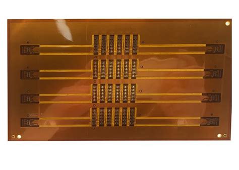
1. Flexible Polyimide PCBs

Flexible Polyimide PCBs, also known as Flex PCBs, are designed to be bendable and conformable. They consist of a thin polyimide film as the base material, with conductive traces and components mounted on top. Flex PCBs offer several advantages, such as:

  • Ability to conform to curved surfaces and tight spaces
  • Reduced weight and space requirements
  • Enhanced durability and resistance to vibration and shock
  • Improved signal integrity due to shorter interconnects

Flexible Polyimide PCBs find applications in various industries, including consumer electronics, medical devices, aerospace, and automotive.

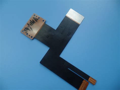
2. Rigid-Flex Polyimide PCBs

Rigid-Flex Polyimide PCBs combine the benefits of both rigid and Flexible PCBs. They consist of rigid PCB sections connected by flexible polyimide interconnects. This hybrid design allows for the integration of multiple PCB Layers and components into a single compact assembly. Rigid-flex PCBs offer several advantages, such as:

  • Reduced size and weight compared to separate rigid and flex PCBs
  • Improved reliability and durability due to fewer interconnects
  • Enhanced signal integrity and reduced electromagnetic interference (EMI)
  • Flexibility in design and layout for complex electronic systems

Rigid-Flex Polyimide PCBs are commonly used in aerospace, military, and medical applications where space constraints and reliability are critical factors.

3. High-Density Interconnect (HDI) Polyimide PCBs

High-Density Interconnect (HDI) Polyimide PCBs are designed to accommodate a large number of components and interconnects in a small form factor. They feature fine-pitch traces, micro-vias, and multiple layers to achieve high component density. HDI Polyimide PCBs offer several benefits, including:

  • Miniaturization of electronic devices
  • Improved signal integrity and reduced signal delay
  • Enhanced thermal management due to better heat dissipation
  • Increased functionality and performance in a compact package

HDI Polyimide PCBs are widely used in smartphones, tablets, wearable devices, and other high-performance electronics.

Applications of Polyimide PCBs

Polyimide PCBs find applications in various industries and sectors due to their exceptional properties and reliability. Let’s explore some of the key application areas:

1. Aerospace and Defense

In the aerospace and defense industry, Polyimide PCBs are extensively used due to their ability to withstand extreme temperatures, vibrations, and harsh environments. Some specific applications include:

  • Avionics systems
  • Satellite communication devices
  • Radar and surveillance equipment
  • Military vehicles and weaponry

Polyimide PCBs provide the necessary reliability and durability to ensure the proper functioning of critical systems in aerospace and defense applications.

2. Automotive Electronics

The automotive industry has seen a significant increase in the use of electronic systems, and Polyimide PCBs play a crucial role in enabling these advancements. Some automotive applications of Polyimide PCBs include:

  • Engine control units (ECUs)
  • Infotainment systems
  • Advanced driver assistance systems (ADAS)
  • Electric vehicle power electronics

Polyimide PCBs offer the required thermal stability, vibration resistance, and electrical performance to withstand the demanding conditions in automotive environments.

3. Medical Devices

Polyimide PCBs are widely used in medical devices due to their biocompatibility, flexibility, and reliability. Some examples of medical applications include:

  • Implantable devices (pacemakers, neurostimulators)
  • Wearable health monitoring devices
  • Diagnostic imaging equipment
  • Surgical instruments

The use of Polyimide PCBs in medical devices ensures patient safety, device longevity, and accurate data acquisition.

4. Consumer Electronics

Consumer electronics is another major application area for Polyimide PCBs. The demand for smaller, lighter, and more functional devices has driven the adoption of Polyimide PCBs in this sector. Some examples include:

  • Smartphones and tablets
  • Wearable devices (smartwatches, fitness trackers)
  • Virtual reality (VR) and augmented reality (AR) devices
  • High-performance gaming systems

Polyimide PCBs enable the miniaturization and performance enhancement of consumer electronic devices while maintaining reliability and durability.

Benefits of Polyimide PCBs

Polyimide PCBs offer several key benefits that make them a preferred choice for various applications. Let’s explore some of these benefits in detail:

1. High Thermal Stability

One of the most significant advantages of Polyimide PCBs is their exceptional thermal stability. Polyimide can withstand temperatures up to 400°C without significant degradation or loss of properties. This thermal stability is crucial in applications where the PCB is exposed to high temperatures, such as in aerospace, automotive, and industrial environments.

2. Excellent Mechanical Properties

Polyimide PCBs exhibit excellent mechanical properties, including high tensile strength, flexibility, and dimensional stability. These properties enable Polyimide PCBs to withstand mechanical stresses, vibrations, and shocks without cracking or delamination. The flexibility of Polyimide PCBs also allows for the design of compact and conformable electronic assemblies.

3. Superior Electrical Insulation

Polyimide offers superior electrical insulation properties, making it an ideal material for PCB fabrication. It has a high dielectric strength, low dielectric constant, and low dissipation factor. These properties ensure reliable electrical performance, reduced signal loss, and minimal crosstalk between adjacent traces. The excellent electrical insulation of Polyimide PCBs is particularly important in high-frequency and high-speed applications.

4. Chemical Resistance

Polyimide PCBs exhibit excellent chemical resistance, making them suitable for use in harsh chemical environments. They can withstand exposure to various solvents, acids, and bases without significant degradation or loss of properties. This chemical resistance is essential in applications where the PCB may come into contact with aggressive chemicals, such as in industrial processes or medical devices.

5. Lightweight and Space-Saving

Polyimide PCBs are lightweight and can be fabricated in thin profiles, making them ideal for applications where weight and space are critical factors. The low density of polyimide allows for the design of lightweight electronic assemblies, which is particularly important in aerospace and portable electronics. The thin profile of Polyimide PCBs also enables the miniaturization of electronic devices and the efficient utilization of available space.

Frequently Asked Questions (FAQs)

  1. Q: What is the maximum operating temperature of Polyimide PCBs?
    A: Polyimide PCBs can withstand temperatures up to 400°C without significant degradation or loss of properties.

  2. Q: Can Polyimide PCBs be used in flexible applications?
    A: Yes, Polyimide PCBs can be designed as flexible PCBs (flex PCBs) or rigid-flex PCBs, allowing them to conform to curved surfaces and tight spaces.

  3. Q: Are Polyimide PCBs suitable for high-frequency applications?
    A: Yes, Polyimide PCBs offer superior electrical insulation properties, including low dielectric constant and low dissipation factor, making them suitable for high-frequency and high-speed applications.

  4. Q: Can Polyimide PCBs be exposed to harsh chemical environments?
    A: Yes, Polyimide PCBs exhibit excellent chemical resistance and can withstand exposure to various solvents, acids, and bases without significant degradation.

  5. Q: What are the advantages of using Polyimide PCBs in medical devices?
    A: Polyimide PCBs offer biocompatibility, flexibility, and reliability, making them suitable for use in medical devices such as implantable devices, wearable health monitoring systems, and diagnostic equipment.

Conclusion

Polyimide PCBs have emerged as a superior choice for a wide range of applications due to their exceptional properties and benefits. Their high thermal stability, excellent mechanical strength, superior electrical insulation, chemical resistance, and lightweight nature make them suitable for demanding environments and high-performance electronics.

From aerospace and defense to automotive, medical devices, and consumer electronics, Polyimide PCBs have found their way into various industries, enabling the development of reliable, durable, and compact electronic systems. As technology continues to advance and the demand for high-performance electronics grows, Polyimide PCBs are expected to play an increasingly important role in shaping the future of electronic design and manufacturing.

By understanding the types, applications, and benefits of Polyimide PCBs, engineers and designers can make informed decisions when selecting the appropriate PCB material for their specific requirements. Whether it’s designing a flexible wearable device, a high-speed communication system, or a rugged automotive control unit, Polyimide PCBs offer the necessary performance, reliability, and versatility to meet the challenges of modern electronics.

PCB Manufacturing Services

Introduction to PCB Manufacturing

Printed Circuit Board (PCB) manufacturing is a crucial process in the electronics industry. It involves the creation of a board that connects electronic components using conductive tracks, pads, and other features etched from copper sheets laminated onto a non-conductive substrate. PCBs are used in almost all electronic devices, from smartphones and computers to industrial equipment and medical devices.

Types of PCB Manufacturing

There are several types of PCB manufacturing, each with its own advantages and disadvantages. The most common types are:

Type Description
Single-sided PCB A PCB with conductive tracks on one side only. Suitable for simple circuits.
Double-sided PCB A PCB with conductive tracks on both sides. Provides more space for components and allows for more complex circuits.
Multi-layer PCB A PCB with multiple layers of conductive tracks separated by insulating layers. Allows for even more complex circuits and higher component density.
Flexible PCB A PCB made from flexible materials that can be bent or folded. Useful for applications where space is limited or the PCB needs to conform to a specific shape.
Rigid-flex PCB A combination of rigid and flexible PCBs. Provides the benefits of both types in a single board.

PCB Manufacturing Process

The PCB manufacturing process involves several steps, each of which must be carried out with precision to ensure the quality and reliability of the final product.

Step 1: Design and Layout

The first step in PCB manufacturing is to design the circuit and create a layout of the PCB. This is typically done using specialized software such as Altium Designer or Eagle. The layout includes the placement of components, the routing of conductive tracks, and the creation of any necessary holes or cutouts.

Step 2: Printing the Circuit Pattern

Once the layout is complete, the next step is to print the circuit pattern onto the PCB substrate. This is typically done using a photoresist process. The substrate is coated with a light-sensitive material and then exposed to light through a photomask that contains the circuit pattern. The exposed areas of the photoresist harden, while the unexposed areas can be washed away.

Step 3: Etching

After the photoresist has been developed, the PCB is placed in an etching solution that removes the copper from the areas not protected by the hardened photoresist. This leaves behind the conductive tracks and pads that make up the circuit.

Step 4: Drilling

Once the etching is complete, any necessary holes are drilled into the PCB. These holes may be used for mounting components or for connecting different layers of the board.

Step 5: Plating

After drilling, the PCB is plated with a thin layer of copper to improve conductivity and protect the exposed copper from oxidation. Additional plating with nickel and gold may also be applied for improved durability and solderability.

Step 6: Solder Mask and Silkscreen

A solder mask is then applied to the PCB to protect the copper tracks from short circuits and oxidation. This is typically a green or blue color. A silkscreen layer is also applied to the board to add labels, logos, and other markings.

Step 7: Surface Finish

Finally, a surface finish is applied to the exposed copper areas of the PCB to protect them from oxidation and improve solderability. Common surface finishes include Hot Air Solder Leveling (HASL), Organic Solderability Preservative (OSP), and Electroless Nickel Immersion Gold (ENIG).

Advantages of PCB Manufacturing Services

Using a professional PCB manufacturing service offers several advantages over in-house production or DIY methods.

Quality and Reliability

Professional PCB manufacturers use state-of-the-art equipment and follow strict quality control procedures to ensure that every board meets the highest standards of quality and reliability. They have the expertise and experience to identify and correct potential issues before they become problems.

Cost Efficiency

While it may seem more cost-effective to produce PCBs in-house, the reality is that professional PCB manufacturing services can often provide a more cost-efficient solution in the long run. They have the economies of scale to purchase materials in bulk and the automation to reduce labor costs.

Faster Turnaround Times

PCB manufacturing services have streamlined processes and dedicated production lines that allow them to produce boards quickly and efficiently. This can be especially important for projects with tight deadlines or for businesses that need to get products to market quickly.

Access to Advanced Technologies

Professional PCB manufacturers invest in the latest technologies and equipment to stay competitive. This means that they can offer advanced features and capabilities that may not be available with in-house production, such as high-density interconnect (HDI) boards or advanced surface finishes.

Choosing a PCB Manufacturing Service

When choosing a PCB manufacturing service, there are several factors to consider to ensure that you get the best possible results for your project.

Experience and Expertise

Look for a PCB manufacturer with a proven track record of success and expertise in the specific type of board you need. Ask for references and examples of previous work to ensure that they have the necessary skills and experience.

Quality Control Procedures

Quality control is critical in PCB manufacturing. Ask about the manufacturer’s quality control procedures and certifications, such as ISO 9001 or UL listing. Make sure that they have a robust testing and inspection process in place to catch any defects or issues before the boards are shipped.

Turnaround Time and Pricing

Consider the manufacturer’s turnaround time and pricing structure. While it may be tempting to choose the cheapest option, keep in mind that quality and reliability should be the top priorities. Look for a manufacturer that can provide a balance of speed, quality, and affordability.

Customer Service and Support

Finally, consider the level of customer service and support offered by the manufacturer. Look for a company that is responsive to your needs and willing to work with you to ensure that your project is a success. Good communication and a partnership approach can go a long way in ensuring a smooth and successful PCB manufacturing process.

Frequently Asked Questions

What is the minimum order quantity for PCB manufacturing?

The minimum order quantity (MOQ) for PCB manufacturing can vary depending on the manufacturer and the specifics of your project. Some manufacturers may have MOQs as low as one or two boards, while others may require a minimum of 100 or more. Be sure to discuss your needs with the manufacturer upfront to ensure that they can accommodate your order.

How long does PCB manufacturing typically take?

The turnaround time for PCB manufacturing can vary depending on the complexity of the board, the manufacturer’s workload, and other factors. Simple boards may be produced in as little as 24 hours, while more complex boards may take several weeks. Be sure to discuss your timeline with the manufacturer upfront and plan accordingly.

What file formats are needed for PCB manufacturing?

Most PCB manufacturers require Gerber files, which are a standard format used in the electronics industry. Gerber files contain all the necessary information for manufacturing the board, including the copper layers, drill holes, and silkscreen. Some manufacturers may also accept other formats such as ODB++ or IPC-2581.

Can I request a prototype before placing a full order?

Yes, most PCB manufacturers offer prototyping services that allow you to test and validate your design before committing to a full production run. This can be a valuable step in ensuring that your board meets your specific needs and requirements.

What certifications should I look for in a PCB manufacturer?

There are several certifications that can indicate a PCB manufacturer’s commitment to quality and reliability. These include ISO 9001 for quality management systems, UL listing for safety, and RoHS compliance for environmental sustainability. Ask the manufacturer about their certifications and what they mean for your specific project.

Conclusion

PCB manufacturing is a complex and highly specialized process that requires expertise, precision, and attention to detail. By understanding the basics of PCB manufacturing and working with a reputable PCB manufacturing service, you can ensure that your electronic projects are successful and reliable.

When choosing a PCB manufacturing service, look for a company with experience, expertise, and a commitment to quality. Consider factors such as turnaround time, pricing, and customer service, and don’t hesitate to ask questions or request prototypes to ensure that your needs are met.

With the right PCB manufacturing partner, you can bring your electronic ideas to life and create products that are innovative, reliable, and successful in the marketplace.

Flexible PCB: Pliable Circuit Boards for Compact Devices

Introduction to Flexible PCB

Flexible printed circuit boards, also known as flex circuits or flexible PCBs, have revolutionized the electronics industry by providing a versatile and compact solution for interconnecting electronic components. Unlike traditional rigid PCBs, flexible PCBs are made from thin, flexible materials that can bend, fold, and twist without damaging the electrical connections. This unique property makes them ideal for applications where space is limited, or where the device needs to conform to a specific shape.

What is a Flexible PCB?

A flexible PCB is a type of printed circuit board that consists of a thin, flexible substrate with conductive traces and components mounted on it. The substrate is typically made from a flexible polymer material, such as polyimide or polyester, and the conductive traces are usually made from copper. The components are attached to the substrate using various methods, such as surface mount technology (SMT) or through-hole mounting.

Advantages of Flexible PCBs

Flexible PCBs offer several advantages over traditional rigid PCBs, including:

  1. Compact size: Flexible PCBs can be bent, folded, and twisted to fit into tight spaces, making them ideal for compact devices such as smartphones, wearables, and medical implants.

  2. Lightweight: The thin, flexible materials used in flexible PCBs make them much lighter than rigid PCBs, which is essential for portable devices and aerospace applications.

  3. High reliability: Flexible PCBs are less prone to mechanical stress and vibration, which can cause failures in rigid PCBs. They also have better thermal management properties, which can improve the overall reliability of the device.

  4. Design flexibility: Flexible PCBs allow designers to create complex, three-dimensional shapes that would be impossible with rigid PCBs. This enables more creative and efficient product designs.

  5. Cost-effective: In some cases, flexible PCBs can be more cost-effective than rigid PCBs, especially for high-volume production runs. They also require fewer connectors and cables, which can further reduce costs.

Types of Flexible PCBs

There are several types of flexible PCBs, each with its own unique properties and applications.

Single-sided Flexible PCBs

Single-sided flexible PCBs have conductive traces on only one side of the substrate. They are the simplest and most cost-effective type of flexible PCB, and are often used in applications where cost is a primary concern.

Double-sided Flexible PCBs

Double-sided flexible PCBs have conductive traces on both sides of the substrate, which allows for more complex circuit designs and higher component density. They are commonly used in applications where space is limited, such as smartphones and wearables.

Multilayer Flexible PCBs

Multilayer flexible PCBs consist of multiple layers of flexible substrate with conductive traces on each layer. They offer the highest level of design flexibility and component density, but are also the most complex and expensive type of flexible PCB. Multilayer flexible PCBs are often used in high-end applications, such as aerospace and medical devices.

Rigid-Flex PCBs

Rigid-flex PCBs are a hybrid of flexible and rigid PCBs, with rigid sections connected by flexible sections. This allows for even greater design flexibility, as the rigid sections can house components that require a stable base, while the flexible sections can bend and fold as needed. Rigid-flex PCBs are commonly used in applications where both flexibility and stability are required, such as automotive electronics and industrial control systems.

Manufacturing Process of Flexible PCBs

The manufacturing process for flexible PCBs is similar to that of rigid PCBs, but with a few key differences.

Material Selection

The first step in manufacturing a flexible PCB is selecting the appropriate materials. The substrate material must be flexible, durable, and able to withstand the intended operating conditions. Common substrate materials include polyimide, polyester, and DuPont’s Pyralux. The conductive traces are typically made from copper, and the thickness of the copper layer can vary depending on the specific application.

Circuit Design

Once the materials have been selected, the next step is to design the circuit. This involves creating a schematic diagram of the circuit, followed by a layout that shows the physical arrangement of the components and traces on the substrate. The layout must take into account the flexibility of the substrate, as well as any mechanical constraints or environmental factors that may affect the performance of the circuit.

Substrate Preparation

Before the circuit can be printed onto the substrate, the substrate must be prepared. This typically involves cleaning the surface to remove any contaminants, followed by the application of an adhesive layer to help the copper traces adhere to the substrate.

Circuit Printing

The actual printing of the circuit onto the substrate can be done using several methods, including screen printing, photolithography, and direct printing. Screen printing involves using a stencil to apply the conductive ink to the substrate, while photolithography uses light to transfer the circuit pattern onto a photosensitive layer on the substrate. Direct printing, also known as inkjet printing, uses a specialized printer to deposit the conductive ink directly onto the substrate.

Etching and Plating

After the circuit has been printed onto the substrate, the next step is to remove any unwanted copper to create the final circuit pattern. This is typically done using a chemical etching process, which selectively removes the copper that is not part of the circuit. In some cases, additional copper may be added to the circuit using an electroplating process to increase the thickness of the traces.

Lamination and Coverlay

Once the circuit has been etched and plated, the next step is to laminate the layers of the flexible PCB together. This involves applying heat and pressure to bond the layers together, creating a single, flexible unit. A coverlay layer may also be added to protect the circuit from damage and provide insulation between the layers.

Cutting and Finishing

The final step in the manufacturing process is to cut the flexible PCB to its final shape and size. This can be done using a variety of methods, including die cutting, laser cutting, and routing. Any final finishes, such as soldermask or silkscreen, are also applied at this stage.

Applications of Flexible PCBs

Flexible PCBs have a wide range of applications across various industries, from consumer electronics to aerospace and beyond.

Consumer Electronics

One of the most common applications for flexible PCBs is in consumer electronics, such as smartphones, tablets, and wearables. The compact size and flexibility of flexible PCBs allow designers to create smaller, more lightweight devices with unique form factors.

Device Flexible PCB Application
Smartphones Connecting displays, cameras, and other components
Smartwatches Conforming to the shape of the watch body
Earbuds Fitting inside the small, curved housing

Medical Devices

Flexible PCBs are also widely used in medical devices, where their flexibility and biocompatibility make them ideal for implantable and wearable devices.

Device Flexible PCB Application
Pacemakers Connecting sensors and electrodes inside the device
Hearing Aids Fitting inside the small, curved housing
Insulin Pumps Connecting sensors and displays in a compact package

Automotive Electronics

In the automotive industry, flexible PCBs are used in a variety of applications, from dashboard displays to engine control modules.

Application Flexible PCB Benefit
Dashboard Displays Conforming to the curved shape of the dashboard
Sensor Arrays Connecting multiple sensors in a compact package
Wiring Harnesses Reducing weight and complexity compared to cables

Aerospace and Defense

Flexible PCBs are also used extensively in aerospace and defense applications, where their lightweight and high reliability are essential.

Application Flexible PCB Benefit
Satellite Systems Reducing weight while maintaining high reliability
Aircraft Avionics Fitting inside tight spaces and conforming to contours
Military Radios Withstanding harsh environmental conditions

Future of Flexible PCBs

As technology continues to advance, the demand for smaller, more complex devices will only continue to grow. This means that flexible PCBs will likely play an even larger role in the electronics industry in the years to come.

Advancements in Materials

One area where we can expect to see significant advancements is in the materials used to manufacture flexible PCBs. Researchers are continually developing new, more advanced materials that offer better flexibility, durability, and electrical performance. For example, some newer materials can stretch and conform to even more complex shapes, opening up new possibilities for product design.

Increased Adoption in Emerging Technologies

Flexible PCBs are also likely to see increased adoption in emerging technologies, such as the Internet of Things (IoT), wearables, and robotics. As these technologies continue to evolve, the demand for smaller, more flexible electronics will only continue to grow.

Integration with Other Manufacturing Techniques

Another area where we may see advancements is in the integration of flexible PCBs with other manufacturing techniques, such as 3D printing and printed electronics. By combining these technologies, designers may be able to create even more complex and customized devices that would not be possible with traditional manufacturing methods.

Frequently Asked Questions (FAQ)

  1. Q: How long do flexible PCBs last compared to rigid PCBs?
    A: The lifespan of a flexible PCB depends on various factors, such as the materials used, the operating conditions, and the level of flexing. In general, a well-designed flexible PCB can last just as long as a rigid PCB in the same application.

  2. Q: Can flexible PCBs be repaired if damaged?
    A: In most cases, flexible PCBs can be repaired using specialized techniques, such as microsoldering or conductive adhesives. However, the repairability depends on the extent and location of the damage, as well as the specific materials and construction of the PCB.

  3. Q: Are flexible PCBs more expensive than rigid PCBs?
    A: The cost of flexible PCBs compared to rigid PCBs depends on several factors, such as the complexity of the design, the materials used, and the volume of production. In some cases, flexible PCBs may be more expensive due to the specialized materials and manufacturing processes required. However, they can also offer cost savings by reducing the need for connectors and cables, and by enabling more compact and efficient product designs.

  4. Q: Can flexible PCBs be used in high-temperature applications?
    A: Yes, some flexible PCBs are designed to withstand high temperatures, using specialized materials such as polyimide or PEEK. These materials can maintain their flexibility and electrical properties even at temperatures up to 400°C.

  5. Q: How do you choose the right type of flexible PCB for a given application?
    A: Choosing the right type of flexible PCB depends on several factors, such as the intended use case, the required flexibility and durability, the complexity of the circuit, and the budget. Single-sided and double-sided flexible PCBs are often sufficient for simpler applications, while multilayer and rigid-flex PCBs may be necessary for more complex designs. It’s important to work with an experienced flexible PCB manufacturer who can help guide you through the selection process based on your specific needs.

Conclusion

Flexible PCBs have revolutionized the electronics industry by enabling smaller, more compact, and more reliable devices across a wide range of applications. From consumer electronics to medical devices and beyond, flexible PCBs offer a versatile and cost-effective solution for interconnecting electronic components in tight spaces and challenging environments.

As technology continues to advance, the demand for flexible PCBs will only continue to grow. With ongoing advancements in materials, manufacturing processes, and integration with other technologies, flexible PCBs are poised to play an even larger role in shaping the future of electronics.

Whether you’re designing a new product or looking to optimize an existing one, flexible PCBs are a powerful tool to have in your arsenal. By understanding the different types of flexible PCBs, their manufacturing processes, and their key applications, you can make informed decisions about how to incorporate them into your designs and stay ahead of the curve in an ever-evolving industry.

Audio low noise preamplifier circuit diagram

What is an Audio preamplifier?

An audio preamplifier, or preamp, is an electronic amplifier that prepares low-level audio signals for further amplification or processing. It is typically used to amplify signals from microphones, instrument pickups, or turntables to a level that can drive a power amplifier or other audio equipment.

The main functions of an audio preamplifier are:

  1. Amplification: Boosting the weak audio signal to a higher level.
  2. Impedance matching: Providing the proper impedance for the input and output devices.
  3. Tone control: Allowing adjustment of bass, midrange, and treble frequencies.
  4. Volume control: Controlling the overall gain of the audio signal.

Importance of Low Noise in Audio Preamplifiers

In an audio system, noise can be introduced at various stages, including the source, the preamplifier, and the power amplifier. A low noise preamplifier is essential to minimize the amount of noise added to the audio signal early in the signal chain.

Noise in an audio preamplifier can come from several sources:

  • Thermal noise: Generated by the random motion of electrons in electronic components.
  • Shot noise: Caused by the discrete nature of electric current.
  • Flicker noise (1/f noise): Occurs due to imperfections in semiconductors.
  • Power supply noise: Introduced by ripple or fluctuations in the power supply.

By minimizing these noise sources, a low noise preamplifier ensures that the audio signal remains clean and free from unwanted artifacts.

Key Design Considerations for a Low Noise Audio Preamplifier

When designing a low noise audio preamplifier, several key factors must be considered:

  1. Component selection: Choose low-noise components, such as metal film resistors and polypropylene capacitors.
  2. Circuit topology: Use a topology that minimizes noise, such as a differential amplifier or a balanced input stage.
  3. Power supply: Provide a clean, stable power supply with good regulation and low ripple.
  4. Grounding: Implement a proper grounding scheme to minimize ground loops and interference.
  5. PCB Layout: Design the printed circuit board (PCB) to minimize crosstalk and interference between components.

Audio Preamplifier Circuit Diagram

Here’s a simple, low noise audio preamplifier circuit diagram using an operational amplifier (op-amp):

[Insert circuit diagram image here]

Components:
– U1: Low-noise op-amp (e.g., NE5532, OPA2134)
– R1, R2: Input resistors (10kΩ)
– R3, R4: Feedback resistors (100kΩ)
– C1, C2: Input coupling capacitors (1μF, film)
– C3, C4: Power supply Bypass Capacitors (100nF, ceramic)
– V+, V-: Positive and negative power supply (±15V)

This circuit uses a non-inverting amplifier configuration with a gain of 11 (R3/R1 + 1). The input coupling capacitors (C1, C2) block any DC offset from the input signal, while the power supply bypass capacitors (C3, C4) help reduce power supply noise.

Op-Amp Selection for Low Noise Performance

The choice of op-amp is crucial for achieving low noise performance in an audio preamplifier. Some popular low-noise op-amps include:

Op-Amp Noise Density (nV/√Hz) Bandwidth (MHz) Input Bias Current (pA)
NE5532 5 10 200
OPA2134 8 8 2
AD797 0.9 8 1
LT1115 2.5 6.5 1

When selecting an op-amp, consider its noise density, bandwidth, and input bias current. Lower noise density and input bias current are preferable for low noise applications. Ensure the op-amp’s bandwidth is sufficient for the desired audio frequency range.

Power Supply Considerations

A clean, stable power supply is essential for low noise performance in an audio preamplifier. Power supply noise can couple into the audio signal through various mechanisms, such as ground loops or power supply rejection ratio (PSRR) limitations of the op-amp.

To minimize power supply noise:

  1. Use Voltage Regulators with good line and load regulation, such as the LM317 (positive) and LM337 (negative).
  2. Use power supply Decoupling Capacitors close to the op-amp’s power supply pins.
  3. Implement a star grounding scheme, where all ground connections meet at a single point to avoid ground loops.
  4. Use separate power supplies or voltage regulators for the analog and digital sections of the circuit, if applicable.

Grounding and Shielding Techniques

Proper grounding and shielding are critical for minimizing noise and interference in an audio preamplifier. Some best practices include:

  1. Use a star grounding scheme, as mentioned earlier.
  2. Separate analog and digital ground planes on the PCB, if applicable.
  3. Use shielded cables for input and output connections to minimize electromagnetic interference (EMI).
  4. Enclose the preamplifier circuit in a metal chassis to provide shielding against external EMI.

PCB Layout Considerations

The PCB layout plays a significant role in the noise performance of an audio preamplifier. Some key considerations include:

  1. Keep signal traces as short as possible to minimize the potential for noise pickup.
  2. Separate analog and digital sections of the circuit to avoid crosstalk.
  3. Use ground planes to provide a low-impedance return path for signals.
  4. Place decoupling capacitors close to the op-amp’s power supply pins.
  5. Avoid routing sensitive signal traces parallel to high-current or noisy traces.

Measuring Noise Performance

To verify the noise performance of your audio preamplifier, you can measure its equivalent input noise (EIN). EIN is the amount of noise present at the input of the preamplifier, expressed in dBu or dBV.

To measure EIN:

  1. Terminate the preamplifier’s input with a low-noise resistor equal to the Input Impedance of the preamplifier.
  2. Measure the output noise voltage using a true RMS voltmeter or a spectrum analyzer.
  3. Calculate the EIN using the following formula:

EIN (dBu) = 20 * log10(V_noise / 0.775) – Gain (dB)

where V_noise is the measured output noise voltage, and Gain is the preamplifier’s voltage gain in dB.

A well-designed low noise audio preamplifier should have an EIN of -120 dBu or better.

Conclusion

Designing a low noise audio preamplifier requires careful consideration of component selection, circuit topology, power supply design, grounding, and PCB layout. By following best practices and selecting appropriate low-noise components, you can create a preamplifier that preserves the quality and clarity of the audio signal, ensuring optimal performance in your audio system.

FAQ

1. What is the difference between a preamplifier and a power amplifier?

A preamplifier is designed to amplify low-level audio signals to a level suitable for further processing or amplification. In contrast, a power amplifier is designed to drive speakers or headphones, providing the necessary current to produce sound.

2. Can I use a single-ended amplifier instead of a differential amplifier for my preamplifier?

While a single-ended amplifier can be used in a preamplifier, a differential amplifier is often preferred due to its better noise rejection and common-mode rejection ratio (CMRR). Differential amplifiers can effectively cancel out noise that is common to both input terminals.

3. What is the importance of input and output impedance in a preamplifier?

Input impedance determines the load that the preamplifier presents to the source device. A high input impedance ensures that the preamplifier does not excessively load the source, preserving signal quality. Output impedance, on the other hand, determines the preamplifier’s ability to drive the next stage in the audio chain. A low output impedance is desirable to minimize signal loss and maintain a consistent frequency response.

4. How can I reduce power supply noise in my preamplifier?

To reduce power supply noise, use voltage regulators with good line and load regulation, place decoupling capacitors close to the op-amp’s power supply pins, and implement a star grounding scheme. Additionally, consider using separate power supplies or voltage regulators for analog and digital sections of the circuit.

5. What is the role of input coupling capacitors in a preamplifier?

Input coupling capacitors (C1 and C2 in the example circuit) are used to block any DC offset from the input signal. This is important because op-amps are designed to amplify AC signals, and DC offsets can cause issues such as output clipping or reduced dynamic range. The capacitors allow the AC audio signal to pass through while blocking the DC component.

PCB Slot: The Perfect Solution for Your Electronics Assembly Needs

What are PCB Slots?

PCB slots are elongated openings or cutouts in a printed circuit board that serve specific purposes, such as:

  • Accommodating connectors or other components
  • Providing mechanical support for the board
  • Facilitating board mounting in enclosures or chassis
  • Improving airflow and heat dissipation
  • Allowing for the passage of cables or wires

These slots come in various shapes and sizes, depending on their intended use and the requirements of the electronic device.

Types of PCB Slots

There are several types of PCB slots, each designed to fulfill specific functions:

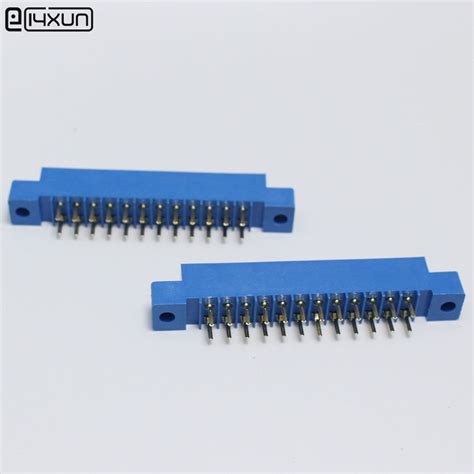
1. Edge Connector Slots

Edge connector slots are located at the edge of a PCB and are used to accommodate connectors that allow the board to interface with other devices or systems. These slots often have gold-plated fingers that make contact with the connector pins, ensuring reliable electrical connections.

2. Mounting Slots

Mounting slots are used to secure the PCB to an enclosure or chassis. These slots allow for the use of screws, standoffs, or other fasteners to hold the board in place, providing mechanical stability and preventing damage from vibration or shock.

3. Tooling Slots

Tooling slots, also known as fiducial slots, are small openings in the PCB that serve as reference points for automated assembly equipment. These slots help align the board correctly during the pick-and-place process, ensuring accurate component placement.

4. Ventilation Slots

Ventilation slots are designed to improve airflow and heat dissipation in electronic devices. By allowing air to circulate more freely around the components, these slots help prevent overheating and extend the lifespan of the electronic components.

5. Cable Slots

Cable slots are openings in the PCB that allow for the passage of cables or wires. These slots are particularly useful in devices that require internal wiring or when connecting multiple boards together.

PCB Slot Design Considerations

When designing PCB slots, several factors must be taken into account to ensure optimal functionality and manufacturability:

1. Slot Dimensions

The dimensions of a PCB slot should be carefully considered based on the specific requirements of the components or connectors it will accommodate. Designers must ensure that the slot is large enough to allow for easy insertion and removal of the component while maintaining a secure fit.

2. Slot Placement

The placement of slots on a PCB is critical for both functionality and manufacturability. Slots should be positioned in a way that allows for efficient routing of traces and the placement of components while avoiding potential manufacturing issues, such as drill breakout or weakening of the board structure.

3. Tolerances

PCB slot tolerances must be carefully specified to ensure proper fit and function. Designers should work closely with manufacturers to determine the appropriate tolerances based on the chosen fabrication process and materials.

4. Material Selection

The choice of PCB material can impact the design and performance of slots. Some materials, such as FR-4, are more prone to chipping or cracking during the slotting process, while others, like polyimide, offer better mechanical stability. Designers should consider the material properties when specifying slot dimensions and tolerances.

5. Manufacturing Processes

Different manufacturing processes can be used to create PCB slots, such as routing, punching, or laser cutting. Each process has its advantages and limitations, and designers should work with manufacturers to select the most appropriate method based on the slot requirements and production volume.

Benefits of Using PCB Slots

Incorporating slots into your PCB design offers several benefits:

1. Enhanced Connectivity

Edge connector slots allow for easy and reliable connection between the PCB and other devices or systems, enabling seamless data transfer and power supply.

2. Improved Mechanical Stability

Mounting slots provide a secure and stable means of attaching the PCB to an enclosure or chassis, reducing the risk of damage from vibration or physical stress.

3. Increased Reliability

Properly designed and manufactured PCB slots contribute to the overall reliability of the electronic device by ensuring secure connections, adequate ventilation, and protection from environmental factors.

4. Simplified Assembly

Tooling slots and well-placed component slots streamline the automated assembly process, reducing the risk of errors and improving production efficiency.

5. Better Thermal Management

Ventilation slots promote better airflow and heat dissipation, helping to prevent component overheating and extend the lifespan of the electronic device.

PCB Slot Materials

PCB slots can be created in various materials, depending on the specific requirements of the application. Some common materials used for PCB slots include:

Material Characteristics
FR-4 Most common PCB material, cost-effective, prone to chipping
Polyimide High mechanical stability, suitable for Flexible PCBs
Aluminum Excellent thermal conductivity, ideal for heat dissipation
Copper High electrical conductivity, often used for grounding slots
Stainless Steel Strong and durable, suitable for high-stress applications

Designing PCB Slots for Manufacturing

To ensure the successful fabrication of PCB slots, designers should follow best practices and work closely with manufacturers. Some key considerations include:

1. Specify Slot Dimensions Clearly

Provide detailed drawings or specifications that clearly indicate the dimensions, tolerances, and placement of each slot on the PCB.

2. Consider Manufacturing Limitations

Work with your manufacturer to understand the limitations of their fabrication processes and equipment, and design slots accordingly.

3. Provide Adequate Clearance

Ensure that there is sufficient clearance around slots for traces, components, and other features to avoid manufacturing issues and signal interference.

4. Use Appropriate File Formats

When submitting PCB designs for manufacturing, use industry-standard file formats, such as Gerber or ODB++, to ensure accurate and efficient communication with the manufacturer.

Frequently Asked Questions (FAQ)

  1. What is the minimum size for a PCB slot?
    The minimum size for a PCB slot depends on the manufacturing process and the capabilities of the fabrication equipment. Typically, slots as small as 0.5mm wide can be achieved with modern PCB manufacturing techniques.

  2. Can PCB slots be used for grounding purposes?
    Yes, PCB slots can be used for grounding purposes. Copper-plated slots, known as grounding slots, provide a low-impedance path to ground, helping to reduce electromagnetic interference (EMI) and improve signal integrity.

  3. How do I choose the right material for my PCB slots?
    The choice of material for PCB slots depends on the specific requirements of your application. Factors to consider include mechanical stability, thermal conductivity, electrical properties, and cost. Consult with your manufacturer to select the most suitable material for your project.

  4. Are there any limitations on the number of slots I can have on a PCB?
    The number of slots on a PCB is limited by the available space and the overall design constraints. Too many slots can weaken the board structure and complicate the routing of traces. Designers should strive for a balance between functionality and manufacturability when incorporating slots into their PCB layouts.

  5. Can PCB slots be added after the board has been fabricated?
    While it is possible to add slots to a PCB after fabrication using techniques like milling or drilling, it is generally not recommended. Adding slots post-fabrication can introduce mechanical stress, damage traces, and compromise the overall integrity of the board. It is best to incorporate slots into the initial PCB design whenever possible.

Conclusion

PCB slots are a vital aspect of electronics assembly, providing a range of functions that contribute to the performance, reliability, and manufacturability of electronic devices. By understanding the types of slots, their design considerations, and the benefits they offer, designers can create PCBs that are optimized for their specific applications.

When designing PCB slots, it is essential to consider factors such as dimensions, placement, tolerances, material selection, and manufacturing processes. By working closely with manufacturers and following best practices, designers can ensure that their PCB slots are fabricated accurately and efficiently, resulting in a high-quality final product.

As the electronics industry continues to evolve, the importance of well-designed PCB slots will only continue to grow. By staying informed about the latest technologies and techniques related to PCB slots, designers can create innovative and reliable electronic devices that meet the ever-changing demands of the market.

Finger Sensors: Types, Construction Forms, Applications, and More

Types of Finger Sensors

There are several types of finger sensors, each with its own unique properties and applications. Let’s take a closer look at some of the most common types:

1. Capacitive Sensors

Capacitive sensors detect the presence or proximity of conductive objects, such as human skin, by measuring changes in capacitance. They are highly sensitive and can detect even the slightest touch or proximity. These sensors are commonly used in touchscreens, touchpads, and other touch-based interfaces.

2. Resistive Sensors

Resistive sensors measure the change in resistance when pressure is applied to their surface. They typically consist of two conductive layers separated by a small gap. When pressure is applied, the layers come into contact, causing a change in resistance. Resistive sensors are often used in pressure-sensitive applications, such as touch screens and pressure-mapping systems.

3. Optical Sensors

Optical sensors use light to detect the presence or movement of objects. They typically consist of a light source (e.g., an LED) and a photodetector. When an object, such as a finger, interrupts the light beam, the photodetector senses the change in light intensity. Optical sensors are used in various applications, including touch screens, gesture recognition, and biometric authentication.

4. Piezoelectric Sensors

Piezoelectric sensors generate an electric charge in response to applied mechanical stress. They are made from piezoelectric materials, such as quartz or certain ceramics. When pressure is applied to the sensor, it generates a measurable electrical signal. Piezoelectric sensors are often used in applications that require high sensitivity and fast response times, such as vibration monitoring and pressure sensing.

5. Temperature Sensors

Temperature sensors, such as thermistors or resistance temperature detectors (RTDs), measure changes in temperature. They are often incorporated into finger sensors to detect the presence of a human finger or to compensate for temperature-related changes in sensor performance. Temperature sensors are essential in applications where temperature monitoring is critical, such as medical devices and industrial processes.

Construction Forms of Finger Sensors

Finger sensors can be constructed in various forms to suit different applications and requirements. Some common construction forms include:

1. Flexible Sensors

Flexible sensors are designed to conform to the shape of the object they are sensing. They are often made from flexible materials, such as polymers or thin metal foils. Flexible sensors are ideal for applications that require conformable or wearable sensing, such as robotics, medical devices, and consumer electronics.

2. Rigid Sensors

Rigid sensors have a fixed, non-deformable structure. They are typically made from solid materials, such as ceramics, metals, or plastics. Rigid sensors are suitable for applications that require a stable and robust sensing platform, such as industrial automation and machine control.

3. Hybrid Sensors

Hybrid sensors combine multiple sensing technologies into a single device. For example, a hybrid sensor might incorporate both capacitive and resistive sensing elements to provide a more comprehensive and accurate measurement. Hybrid sensors are often used in complex applications that require multi-parameter sensing, such as medical diagnostics and environmental monitoring.

Applications of Finger Sensors

Finger sensors find applications in a wide range of industries and domains. Some notable applications include:

1. Consumer Electronics

Finger sensors are ubiquitous in consumer electronics, particularly in devices with touch-based interfaces. Smartphones, tablets, laptops, and smartwatches all rely on finger sensors to detect user input and enable intuitive interaction. Capacitive touch screens, for example, use an array of capacitive sensors to detect the position and movement of a user’s fingers.

2. Medical Devices

Finger sensors play a crucial role in various medical devices, from patient monitoring systems to diagnostic tools. For example, pulse oximeters use optical sensors to measure the oxygen saturation of a patient’s blood by detecting changes in light absorption through the fingertip. Other medical applications include blood pressure monitoring, temperature measurement, and biometric authentication.

3. Industrial Automation

In industrial settings, finger sensors are used to monitor and control various processes and machinery. Pressure sensors, for instance, can detect the force applied by robotic grippers, ensuring precise object manipulation. Temperature sensors can monitor the temperature of materials during manufacturing processes, ensuring optimal conditions and product quality.

4. Automotive Systems

Finger sensors are increasingly being integrated into automotive systems to enhance user experience and safety. Capacitive touch sensors, for example, are used in infotainment systems to provide a seamless and intuitive user interface. Pressure sensors can detect the presence of a driver’s hands on the steering wheel, enabling advanced driver assistance systems (ADAS) to alert the driver if their hands are not in the proper position.

5. Biometric Authentication

Finger sensors are a key component in biometric authentication systems, particularly in fingerprint recognition. Optical, capacitive, and ultrasonic sensors are commonly used to capture high-resolution images of a user’s fingerprint, which can then be compared against a stored template for authentication purposes. Biometric authentication is widely used in smartphones, laptops, and access control systems to provide secure and convenient user identification.

Finger Sensor Performance Metrics

When selecting a finger sensor for a specific application, several performance metrics should be considered. These metrics help to evaluate the sensor’s capabilities and suitability for the intended use case. Some important performance metrics include:

1. Sensitivity

Sensitivity refers to the minimum input signal required to produce a detectable output signal. In the context of finger sensors, sensitivity determines how responsive the sensor is to touch, pressure, or other input stimuli. Higher sensitivity allows the sensor to detect even the slightest changes in input, making it suitable for applications that require precise and accurate measurements.

2. Resolution

Resolution refers to the smallest change in input signal that can be detected by the sensor. For example, in a pressure sensor, resolution determines the smallest pressure difference that can be distinguished. Higher resolution enables the sensor to capture more detailed and nuanced changes in input, which is essential for applications that require fine-grained measurements.

3. Response Time

Response time is the time taken by the sensor to react to a change in input signal. Faster response times are critical in applications that require real-time feedback or rapid decision-making, such as touch screens and interactive systems. Slower response times may be acceptable in applications where the input signal changes slowly or where immediate feedback is not necessary.

4. Durability

Durability refers to the sensor’s ability to withstand repeated use and exposure to environmental factors, such as temperature, humidity, and mechanical stress. In applications where the sensor is subject to frequent use or harsh conditions, such as industrial automation or outdoor monitoring, high durability is essential to ensure reliable performance and long service life.

5. Power Consumption

Power consumption is a crucial consideration in battery-powered or energy-constrained applications, such as wearable devices and wireless sensor networks. Lower power consumption allows the sensor to operate for longer periods without requiring frequent battery replacements or recharging. Power-efficient sensor designs and low-power communication protocols can help to minimize power consumption and extend battery life.

Future Trends and Developments

As technology advances and new applications emerge, finger sensors are continually evolving to meet the changing needs of various industries. Some notable trends and developments in finger sensor technology include:

1. Miniaturization

The trend towards miniaturization is driving the development of smaller, more compact finger sensors. Miniaturized sensors can be easily integrated into wearable devices, such as smartwatches and fitness trackers, enabling continuous and unobtrusive monitoring of user activity and health parameters. Advances in microelectromechanical systems (MEMS) technology and flexible electronics are enabling the fabrication of highly miniaturized and conformable sensors.

2. Integration with Artificial Intelligence (AI)

The integration of finger sensors with AI algorithms is enabling the development of more intelligent and adaptive sensing systems. AI-powered sensors can learn from user behavior and preferences, adapting their performance and functionality to provide a more personalized and intuitive user experience. For example, AI-enhanced touch screens can anticipate user intentions and provide context-aware assistance, improving the overall usability and efficiency of the device.

3. Wireless Connectivity

The proliferation of wireless communication technologies, such as Bluetooth Low Energy (BLE) and Wi-Fi, is enabling the development of wireless finger sensors. Wireless sensors can communicate with other devices and systems without the need for physical connections, providing greater flexibility and mobility. Wireless finger sensors are particularly useful in applications where the sensor needs to be remotely monitored or controlled, such as in healthcare and industrial settings.

4. Multi-Modal Sensing

The integration of multiple sensing modalities into a single finger sensor is becoming increasingly common. Multi-modal sensors can measure multiple parameters simultaneously, providing a more comprehensive and holistic view of the sensed environment. For example, a multi-modal finger sensor might incorporate pressure, temperature, and humidity sensing elements, enabling the device to monitor a wide range of environmental conditions. Multi-modal sensing is particularly useful in applications where multiple parameters need to be monitored and correlated, such as in medical diagnostics and environmental monitoring.

5. Sustainable and Eco-Friendly Materials

As environmental concerns become more pressing, there is a growing demand for sustainable and eco-friendly materials in finger sensor construction. Researchers are exploring the use of biodegradable and recyclable materials, such as organic polymers and paper-based substrates, to reduce the environmental impact of sensor production and disposal. The development of sustainable finger sensors not only benefits the environment but also aligns with the increasing consumer preference for eco-friendly products.

Frequently Asked Questions (FAQ)

1. What is the difference between capacitive and resistive touch sensors?

Capacitive touch sensors detect the presence of conductive objects, such as human skin, by measuring changes in capacitance. They are highly sensitive and can detect even the slightest touch or proximity. Resistive touch sensors, on the other hand, measure the change in resistance when pressure is applied to their surface. They typically consist of two conductive layers separated by a small gap, and when pressure is applied, the layers come into contact, causing a change in resistance.

2. Can finger sensors be used for biometric authentication?

Yes, finger sensors, particularly optical, capacitive, and ultrasonic sensors, are commonly used for biometric authentication, especially in fingerprint recognition. These sensors capture high-resolution images of a user’s fingerprint, which can then be compared against a stored template for authentication purposes. Biometric authentication using finger sensors is widely used in smartphones, laptops, and access control systems to provide secure and convenient user identification.

3. What are the advantages of flexible finger sensors?

Flexible finger sensors offer several advantages over rigid sensors. They can conform to the shape of the object they are sensing, making them ideal for applications that require conformable or wearable sensing, such as robotics, medical devices, and consumer electronics. Flexible sensors can also provide a more comfortable and ergonomic user experience, as they can adapt to the contours of the human body. Additionally, flexible sensors are often more durable and resistant to mechanical stress compared to rigid sensors, as they can bend and deform without breaking.

4. How do finger sensors contribute to industrial automation?

Finger sensors play a crucial role in industrial automation by enabling the monitoring and control of various processes and machinery. Pressure sensors, for example, can detect the force applied by robotic grippers, ensuring precise object manipulation. Temperature sensors can monitor the temperature of materials during manufacturing processes, ensuring optimal conditions and product quality. By providing accurate and real-time data on various parameters, finger sensors help to improve the efficiency, reliability, and safety of industrial operations.

5. What are the key considerations when selecting a finger sensor for a specific application?

When selecting a finger sensor for a specific application, several key considerations should be taken into account. These include the sensor’s sensitivity, resolution, response time, durability, and power consumption. The choice of sensor type (e.g., capacitive, resistive, optical) and construction form (e.g., flexible, rigid) will depend on the specific requirements of the application. Other factors to consider include the sensor’s compatibility with the target environment, its cost, and its ease of integration with existing systems. It is essential to carefully evaluate the sensor’s performance metrics and specifications to ensure that it meets the demands of the intended use case.

Conclusion

Finger sensors are versatile and essential components that find applications in a wide range of industries, from consumer electronics and medical devices to industrial automation and automotive systems. By detecting and measuring various parameters, such as pressure, temperature, and touch, finger sensors enable devices to respond to human input and environmental changes, providing a more intuitive and efficient user experience.

This comprehensive article has explored the different types of finger sensors, including capacitive, resistive, optical, piezoelectric, and temperature sensors, along with their construction forms, such as flexible, rigid, and hybrid sensors. We have also discussed the various applications of finger sensors, highlighting their importance in consumer electronics, medical devices, industrial automation, automotive systems, and biometric authentication.

Furthermore, we have examined the key performance metrics to consider when selecting a finger sensor, including sensitivity, resolution, response time, durability, and power consumption. Looking towards the future, we have identified several trends and developments in finger sensor technology, such as miniaturization, integration with artificial intelligence, wireless connectivity, multi-modal sensing, and the use of sustainable and eco-friendly materials.

As technology continues to advance, finger sensors will undoubtedly play an increasingly important role in shaping the way we interact with devices and the environment around us. By understanding the types, construction forms, applications, and performance metrics of finger sensors, engineers, designers, and researchers can develop more innovative and effective solutions that leverage the full potential of these essential components.

Sensor Type Sensing Principle Key Characteristics Common Applications
Capacitive Detects changes in capacitance caused by conductive objects High sensitivity, can detect proximity and light touch Touchscreens, touchpads, proximity sensing
Resistive Measures change in resistance when pressure is applied Detects applied pressure, typically consists of two conductive layers Pressure-sensitive touchscreens, pressure mapping
Optical Uses light to detect the presence or movement of objects Consists of a light source and photodetector, can detect interruptions in light beam Touchscreens, gesture recognition, biometric authentication
Piezoelectric Generates electric charge in response to applied mechanical stress High sensitivity, fast response times, made from piezoelectric materials Vibration monitoring, pressure sensing
Temperature Measures changes in temperature using thermistors or RTDs Detects the presence of a human finger, compensates for temperature-related changes in sensor performance Medical devices, industrial processes, environmental monitoring

PCB Layout Design Service

Introduction to PCB Layout Design

Printed Circuit Board (PCB) layout design is a crucial step in the development of electronic devices. It involves the arrangement of components and the routing of traces on a PCB to ensure optimal performance, reliability, and manufacturability. A well-designed PCB layout can make the difference between a successful product and one that fails to meet expectations.

In this article, we will explore the various aspects of PCB layout design, including the tools and techniques used by PCB layout designers, the importance of following design rules and guidelines, and the benefits of using a professional PCB layout design service.

What is PCB Layout?

PCB layout refers to the process of arranging electronic components and routing the connections between them on a printed circuit board. The goal of PCB layout is to create a design that is functional, reliable, and manufacturable while also meeting the specific requirements of the intended application.

A typical PCB layout includes the following elements:

  • Components: The electronic components that make up the circuit, such as resistors, capacitors, integrated circuits (ICs), and connectors.
  • Traces: The conductive paths that connect the components on the PCB.
  • Vias: The holes drilled through the PCB to allow traces to connect between layers.
  • Pads: The exposed areas of copper on the PCB where components are soldered.
  • Silkscreen: The text and symbols printed on the PCB to identify components and provide assembly instructions.

The Importance of Proper PCB Layout Design

Proper PCB layout design is essential for several reasons:

  1. Functionality: A well-designed PCB layout ensures that the circuit functions as intended, with minimal signal integrity issues, crosstalk, and electromagnetic interference (EMI).

  2. Reliability: Proper component placement and trace routing can help minimize thermal stress, mechanical stress, and other factors that can impact the long-term reliability of the PCB.

  3. Manufacturability: A PCB layout that follows design rules and guidelines is easier to manufacture, with fewer defects and higher yields.

  4. Cost: An optimized PCB layout can help reduce manufacturing costs by minimizing the size of the board, the number of layers, and the complexity of the assembly process.

PCB Layout Design Tools and Software

To create a PCB layout, designers use specialized software tools that allow them to place components, route traces, and verify the design against a set of design rules. Some of the most popular PCB layout design tools include:

  1. Altium Designer: A powerful and feature-rich PCB design tool used by many professional designers.

  2. Cadence Allegro: A high-end PCB design solution used in the aerospace, defense, and automotive industries.

  3. KiCad: A free and open-source PCB design tool that is popular among hobbyists and small businesses.

  4. EAGLE: A widely used PCB design tool that offers a free version for non-commercial use.

  5. OrCAD: A comprehensive PCB design solution that includes schematic capture, simulation, and layout tools.

These tools offer a range of features and capabilities, including:

  • Schematic capture: The ability to create and edit schematic diagrams of the circuit.
  • Component libraries: Extensive libraries of component footprints and symbols.
  • Auto-routing: Automated tools for routing traces between components.
  • Design rule checking (DRC): Automated checks to ensure that the layout meets the specified design rules.
  • 3D visualization: The ability to view the PCB layout in 3D to check for clearances and mechanical fit.

PCB Layout Design Guidelines and Best Practices

To create a successful PCB layout, designers must follow a set of guidelines and best practices that help ensure the functionality, reliability, and manufacturability of the board. Some of the key guidelines include:

Component Placement

  • Place components in a logical and organized manner, grouping related components together.
  • Consider the flow of signals through the circuit and place components to minimize the length of traces.
  • Ensure that components are oriented correctly and have sufficient clearance for assembly and soldering.

Trace Routing

  • Use the shortest and most direct path possible for each trace to minimize signal integrity issues and reduce EMI.
  • Avoid sharp corners and angles in traces, which can cause signal reflections and EMI.
  • Maintain consistent trace widths and spacing to ensure proper impedance and minimize crosstalk.
  • Use ground planes and power planes to provide low-impedance return paths for signals and reduce EMI.

Grounding and Power Distribution

  • Use a solid ground plane to provide a low-impedance return path for signals and minimize EMI.
  • Provide adequate power distribution to all components, using wide traces or power planes to minimize voltage drop and ensure reliable operation.
  • Use decoupling capacitors near power pins of ICs to reduce noise and ensure stable power delivery.

Signal Integrity

  • Minimize the length of high-speed traces to reduce signal integrity issues such as reflections, ringing, and crosstalk.
  • Use appropriate termination techniques, such as series termination or parallel termination, to match the impedance of the trace to the source and load.
  • Use differential pairs for high-speed signals to minimize EMI and improve signal quality.

Thermal Management

  • Consider the power dissipation of components and provide adequate cooling, such as thermal vias or heatsinks, to prevent overheating.
  • Place temperature-sensitive components away from heat-generating components to minimize thermal stress.

Manufacturing Considerations

  • Follow the design rules and guidelines provided by the PCB manufacturer to ensure manufacturability and minimize defects.
  • Provide adequate clearances and tolerances for component placement, trace routing, and drill holes.
  • Use standard component packages and footprints whenever possible to minimize custom tooling and reduce manufacturing costs.

The Benefits of Using a Professional PCB Layout Design Service

While it is possible for individuals and small businesses to design their own PCB layouts using the tools and guidelines mentioned above, there are several benefits to using a professional PCB layout design service:

  1. Expertise: Professional PCB layout designers have the knowledge, skills, and experience to create optimized layouts that meet the specific requirements of each project.

  2. Time savings: Outsourcing PCB layout design allows businesses to focus on their core competencies while leaving the complex and time-consuming task of PCB layout to the experts.

  3. Cost savings: A professional PCB layout design service can help minimize manufacturing costs by creating layouts that are optimized for the specific manufacturing process and volume.

  4. Quality assurance: Professional PCB layout designers use industry-standard tools and follow strict quality control processes to ensure that each layout meets the highest standards of functionality, reliability, and manufacturability.

  5. Scalability: A professional PCB layout design service can handle projects of any size and complexity, from simple single-layer boards to complex multi-layer designs with high-speed signals and advanced packaging requirements.

Choosing the Right PCB Layout Design Service

When choosing a PCB layout design service, there are several factors to consider:

  1. Experience: Look for a service provider with extensive experience in PCB layout design, particularly in the specific industry or application area of your project.

  2. Capabilities: Ensure that the service provider has the tools, expertise, and resources to handle your specific project requirements, such as high-speed design, advanced packaging, or flex PCBs.

  3. Communication: Choose a service provider that communicates clearly and promptly, and is responsive to your needs and feedback throughout the project.

  4. Quality: Look for a service provider with a proven track record of delivering high-quality PCB layouts that meet or exceed customer expectations.

  5. Cost: Consider the cost of the service in relation to the value it provides, taking into account factors such as expertise, quality, and turnaround time.

Conclusion

PCB layout design is a critical step in the development of electronic devices, with significant impacts on functionality, reliability, manufacturability, and cost. By following best practices and guidelines, and using the right tools and expertise, it is possible to create optimized PCB layouts that meet the specific requirements of each project.

For businesses and individuals who lack the time, resources, or expertise to design their own PCB layouts, using a professional PCB layout design service can provide significant benefits, including improved quality, faster turnaround times, and lower manufacturing costs.

By choosing the right PCB layout design service and working closely with the service provider throughout the project, businesses can ensure that their electronic products are designed and manufactured to the highest standards of quality and reliability.

FAQ

What is the difference between PCB layout and PCB design?

PCB layout refers specifically to the process of arranging components and routing traces on a PCB, while PCB design encompasses the entire process of designing a PCB, including schematic capture, component selection, and layout.

What are the most important factors to consider when designing a PCB layout?

The most important factors to consider when designing a PCB layout include:

  • Component placement and orientation
  • Trace routing and spacing
  • Grounding and power distribution
  • Signal integrity and EMI reduction
  • Thermal management
  • Manufacturing considerations, such as design rules and tolerances

Can I design my own PCB layout without using a professional service?

Yes, it is possible to design your own PCB layout using specialized software tools and following best practices and guidelines. However, for complex or high-performance designs, or for businesses that lack the time or expertise to design their own layouts, using a professional PCB layout design service can provide significant benefits.

How long does it typically take to complete a PCB layout design?

The time required to complete a PCB layout design varies depending on the complexity of the design, the number of components and layers, and the specific requirements of the project. Simple designs may be completed in a few days, while complex designs may take several weeks or even months.

How much does a professional PCB layout design service typically cost?

The cost of a professional PCB layout design service varies depending on the complexity of the design, the experience and expertise of the service provider, and other factors such as turnaround time and manufacturing requirements. In general, prices can range from a few hundred dollars for simple designs to several thousand dollars or more for complex, high-performance designs. It is important to consider the cost of the service in relation to the value it provides, taking into account factors such as quality, reliability, and manufacturability.

Factor Consideration
Component Placement Place components in a logical and organized manner, grouping related components together.
Trace Routing Use the shortest and most direct path possible for each trace to minimize signal integrity issues and reduce EMI.
Grounding and Power Distribution Use a solid ground plane to provide a low-impedance return path for signals and minimize EMI.
Signal Integrity Minimize the length of high-speed traces to reduce signal integrity issues such as reflections, ringing, and crosstalk.
Thermal Management Consider the power dissipation of components and provide adequate cooling, such as thermal vias or heatsinks, to prevent overheating.
Manufacturing Considerations Follow the design rules and guidelines provided by the PCB manufacturer to ensure manufacturability and minimize defects.

PCB Design Software The First Step to a New PC Board

Introduction to PCB Design

Printed Circuit Board (PCB) design is a crucial step in the development of electronic devices. It involves the creation of a layout that connects various electronic components to form a functional circuit. PCB design software is essential for this process, as it allows designers to create, simulate, and optimize their designs before moving on to fabrication.

In this article, we will explore the world of PCB design software, its features, and how it can help you create a new PC board. We will also discuss the various types of PCB design software available in the market and their pros and cons.

What is PCB Design Software?

PCB design software is a computer-aided design (CAD) tool that allows electronic engineers and designers to create, edit, and simulate PCB Layouts. It provides a graphical interface for placing components, routing traces, and defining the board’s shape and size.

PCB design software typically includes the following features:

  • Schematic capture
  • Component library management
  • Board layout and routing
  • Design rule checking (DRC)
  • 3D visualization
  • Gerber File Generation

These features enable designers to create accurate and efficient PCB layouts that meet the requirements of their electronic devices.

Types of PCB Design Software

There are several types of PCB design software available in the market, each with its own set of features and capabilities. Some of the most common types include:

1. Desktop PCB Design Software

Desktop PCB design software is installed on a local computer and provides a standalone environment for creating PCB layouts. Examples of desktop PCB design software include:

  • Altium Designer
  • Cadence OrCAD
  • Mentor Graphics PADS
  • Eagle PCB

These software packages offer a wide range of features and are suitable for both hobbyists and professional designers.

2. Cloud-Based PCB Design Software

Cloud-based PCB design software is accessed through a web browser and allows designers to create and collaborate on PCB layouts from anywhere in the world. Examples of cloud-based PCB design software include:

  • Upverter
  • CircuitMaker
  • EasyEDA

Cloud-based PCB design software is often more affordable and accessible than desktop software, making it a popular choice for hobbyists and small businesses.

3. Open-Source PCB Design Software

Open-source PCB design software is freely available and allows users to modify and distribute the source code. Examples of open-source PCB design software include:

  • KiCad
  • gEDA
  • FreePCB

Open-source PCB design software is often less feature-rich than commercial software but can be a good choice for those on a tight budget or with specific customization needs.

Choosing the Right PCB Design Software

When choosing PCB design software, there are several factors to consider:

1. Features

Consider the features offered by each software package and how they align with your design requirements. Some key features to look for include:

  • Schematic capture
  • Component library management
  • Board layout and routing
  • Design rule checking (DRC)
  • 3D visualization
  • Gerber file generation

2. Ease of Use

Choose software that is easy to learn and use, especially if you are new to PCB design. Look for software with a user-friendly interface and helpful documentation.

3. Compatibility

Ensure that the software you choose is compatible with your operating system and any other tools you plan to use in your design process.

4. Price

Consider your budget when choosing PCB design software. While some high-end packages can be expensive, there are also affordable and open-source options available.

Getting Started with PCB Design Software

Once you have chosen your PCB design software, it’s time to get started with your design. Here are the basic steps involved in creating a new PC board using PCB design software:

1. Create a Schematic

The first step in PCB design is to create a schematic of your circuit. This involves placing components and connecting them with wires to form a logical representation of your circuit.

2. Create a Component Library

Next, you will need to create a component library that contains the footprints and symbols for the components used in your design. Many PCB design software packages include pre-made libraries, but you may need to create custom components for specific parts.

3. Create a Board Layout

Once your schematic is complete, you can create a board layout by placing components and routing traces between them. PCB design software typically includes tools for automatically routing traces and optimizing the layout for manufacturability.

4. Perform Design Rule Checks

Before finalizing your design, it’s important to perform design rule checks (DRC) to ensure that your layout meets the manufacturing requirements. This includes checking for minimum trace widths, clearances, and other design rules.

5. Generate Gerber Files

Finally, you will need to generate Gerber files that can be sent to a PCB manufacturer for fabrication. Gerber files are industry-standard files that contain all the information needed to manufacture your PCB.

Advanced PCB Design Techniques

Once you have mastered the basics of PCB design, there are several advanced techniques you can use to optimize your designs:

1. High-Speed Design

High-speed design involves techniques for routing high-frequency signals on a PCB while minimizing noise and interference. This includes using controlled impedance traces, minimizing crosstalk, and using ground planes to provide a low-impedance return path.

2. RF Design

RF (radio frequency) design involves techniques for designing PCBs that operate at high frequencies, such as those used in wireless communication devices. This includes using specialized components and layout techniques to minimize signal loss and interference.

3. Flexible PCB Design

Flexible PCBs are designed to bend and flex without breaking, making them ideal for applications where space is limited or where the PCB needs to conform to a specific shape. Designing flexible PCBs requires special considerations for material selection, trace routing, and mechanical stress.

4. HDI Design

HDI (high-density interconnect) design involves techniques for creating PCBs with very small features and high component density. This includes using microvias, blind and buried vias, and fine-pitch components to maximize space utilization.

Frequently Asked Questions (FAQ)

1. What is the best PCB design software for beginners?

For beginners, we recommend using a user-friendly PCB design software such as Eagle PCB or KiCad. These software packages offer a simple interface and helpful documentation to guide you through the design process.

2. How much does PCB design software cost?

The cost of PCB design software varies widely depending on the features and capabilities offered. Desktop PCB design software can range from a few hundred to several thousand dollars, while cloud-based and open-source options are often more affordable or even free.

3. Can I use PCB design software on a Mac?

Yes, many PCB design software packages are available for both Windows and Mac operating systems. However, some software may have limited features or compatibility on Mac compared to Windows.

4. How long does it take to learn PCB design software?

The time it takes to learn PCB design software depends on your prior experience with electronics and computer-aided design. For beginners, it may take several weeks or months to become proficient with the software, while experienced designers may be able to pick it up more quickly.

5. Can I use PCB design software to create multi-layer PCBs?

Yes, most PCB design software packages support the creation of multi-layer PCBs. However, designing multi-layer PCBs requires additional considerations for layer stackup, via placement, and signal integrity.

Conclusion

PCB design software is an essential tool for anyone looking to create a new PC board. Whether you are a hobbyist or a professional designer, there is a PCB design software package that can meet your needs and budget.

When choosing PCB design software, consider the features, ease of use, compatibility, and price to find the best fit for your project. Once you have chosen your software, follow the basic steps of creating a schematic, component library, board layout, and performing design rule checks to ensure a successful design.

As you become more proficient with PCB design software, you can explore advanced techniques such as high-speed design, RF design, flexible PCB design, and HDI design to optimize your designs for specific applications.

With the right PCB design software and techniques, you can create a new PC board that meets your requirements and exceeds your expectations.

PCB Design Software Type Operating System Price Range
Altium Designer Desktop Windows $$$$
Cadence OrCAD Desktop Windows $$$$
Mentor Graphics PADS Desktop Windows $$$$
Eagle PCB Desktop Windows, Mac, Linux $$
KiCad Open-Source Windows, Mac, Linux Free
Upverter Cloud-Based Web Browser $
CircuitMaker Cloud-Based Web Browser Free
EasyEDA Cloud-Based Web Browser Free