What is a Data Bus?
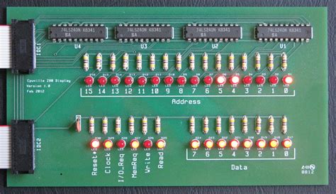
A data bus is a digital communication system that transfers data between components inside a computer or between computers. It consists of a set of parallel wires or traces that carry multiple bits simultaneously. The bus width, which is the number of parallel wires, determines the amount of data that can be transferred at once.
Data buses are classified into different types based on their functionality and the components they connect:
| Bus Type | Description |
|---|---|
| System Bus | Connects the CPU, memory, and other core components |
| Address Bus | Carries memory addresses from the CPU to memory |
| Control Bus | Carries control signals and clock signals |
| Expansion Bus | Connects peripheral devices to the motherboard |
Bus Architecture
The architecture of a data bus plays a crucial role in determining its performance and efficiency. There are several bus architectures used in modern computer systems:
Single Bus Architecture
In a single bus architecture, all components share a common bus for communication. This architecture is simple and cost-effective but may suffer from contention issues when multiple devices attempt to use the bus simultaneously.
Hierarchical Bus Architecture
A hierarchical bus architecture organizes the buses into multiple levels, with each level serving a specific purpose. For example:
| Level | Bus | Description |
|---|---|---|
| Level 1 | Local Bus | Connects the CPU and cache memory |
| Level 2 | System Bus | Connects the CPU, main memory, and other core components |
| Level 3 | Expansion Bus | Connects peripheral devices |
This architecture provides better performance by reducing bus contention and allowing faster communication between closely related components.
Backplane Bus Architecture
In a backplane bus architecture, multiple printed circuit boards (PCBs) are connected to a common backplane, which contains the data bus. This architecture is commonly used in modular systems, such as blade servers and industrial control systems.
Bus Protocols
Bus protocols define the rules and conventions for communication over a data bus. They specify the format of the data, the timing of signals, and the handshaking mechanisms between devices. Some common bus protocols include:
-
PCI (Peripheral Component Interconnect): A high-speed bus used for connecting peripheral devices to the motherboard.
-
USB (Universal Serial Bus): A versatile bus that supports hot-plugging and is widely used for connecting external devices.
-
I2C (Inter-Integrated Circuit): A simple, two-wire bus used for communication between integrated circuits.
-
SPI (Serial Peripheral Interface): A synchronous serial bus used for short-distance communication between microcontrollers and peripherals.

Bus Width and Data Transfer
The width of a data bus determines the number of bits that can be transferred simultaneously. Common bus widths include:
| Bus Width | Description |
|---|---|
| 8-bit | Transfers 8 bits (1 byte) at a time |
| 16-bit | Transfers 16 bits (2 bytes) at a time |
| 32-bit | Transfers 32 bits (4 bytes) at a time |
| 64-bit | Transfers 64 bits (8 bytes) at a time |
Wider buses can transfer more data per clock cycle, resulting in higher throughput. However, they also require more physical connections and consume more power.
Bus Arbitration
When multiple devices are connected to a shared bus, bus arbitration mechanisms are used to manage access to the bus and prevent conflicts. There are two main types of bus arbitration:
-
Centralized Arbitration: A dedicated arbiter circuit grants bus access to requesting devices based on a predefined priority scheme.
-
Distributed Arbitration: Each device on the bus follows a set of rules to determine when it can access the bus, without the need for a central arbiter.
Common bus arbitration schemes include:
- Daisy Chain: Devices are connected in a chain, and the bus grant signal is passed from one device to the next.
- Parallel Priority: Each device is assigned a unique priority level, and the device with the highest priority wins bus access.
- CSMA/CD (Carrier Sense Multiple Access with Collision Detection): Devices listen to the bus before transmitting and retransmit if a collision occurs.
Bus Timing and Synchronization
Proper timing and synchronization are essential for reliable data transfer over a bus. Bus timing is controlled by a clock signal, which determines when data is valid and when it can be sampled.
Synchronous Bus
In a synchronous bus, all devices operate on the same clock signal. Data transfer occurs at specific clock edges, and devices must adhere to strict timing requirements. Examples of synchronous buses include PCI and DDR memory buses.
Asynchronous Bus
An asynchronous bus does not rely on a shared clock signal. Instead, handshaking signals are used to coordinate data transfer between devices. Examples of asynchronous buses include I2C and USB.
Bus Buffering and Driving
To ensure signal integrity and reliable data transfer, data buses employ buffering and driving techniques:
-
Buffering: Bus buffers are used to isolate the bus from the connected devices, reducing loading effects and improving signal quality.
-
Driving: Bus drivers are used to amplify signals and provide sufficient current to drive the bus. They help maintain signal levels and minimize signal distortion.
Bus Performance Metrics
Several metrics are used to evaluate the performance of a data bus:
-
Bandwidth: The maximum amount of data that can be transferred over the bus per unit time, typically measured in bits per second (bps) or bytes per second (Bps).
-
Latency: The time delay between initiating a data transfer and the actual transfer of data.
-
Throughput: The actual amount of data transferred over the bus per unit time, considering overheads and bus utilization.
Bus Topology
The physical arrangement of devices on a bus is known as bus topology. Common bus topologies include:
-
Linear Bus: Devices are connected in a linear fashion, with each device having a unique address.
-
Daisy Chain: Devices are connected in a chain, with the output of one device connected to the input of the next.
-
Star Bus: Devices are connected to a central hub or switch, which manages communication between devices.
Error Detection and Correction
To ensure data integrity, data buses incorporate error detection and correction mechanisms:
-
Parity: An extra bit is added to each data word to detect single-bit errors. Even parity and odd parity schemes are commonly used.
-
ECC (Error Correction Code): Additional bits are added to each data word to detect and correct single-bit errors and detect multi-bit errors.
-
CRC (Cyclic Redundancy Check): A checksum is calculated over a block of data and appended to the end. The receiving device recalculates the checksum to verify data integrity.
Bus Interfaces and Standards
There are numerous bus interfaces and standards used in computer systems and electronic devices. Some notable examples include:
-
PCI Express (PCIe): A high-speed serial bus used for connecting peripheral devices to the motherboard.
-
AGP (Accelerated Graphics Port): A dedicated bus for connecting graphics cards to the motherboard.
-
SATA (Serial ATA): A bus interface for connecting storage devices, such as hard drives and SSDs.
-
IEEE 1394 (FireWire): A high-speed serial bus for connecting multimedia devices and external storage.
-
CAN (Controller Area Network): A robust bus standard used in automotive and industrial control systems.
Frequently Asked Questions (FAQ)
1. What is the difference between a data bus and an address bus?
A data bus carries the actual data being transferred between components, while an address bus carries the memory addresses specifying the source or destination of the data.
2. Can devices with different bus widths communicate with each other?
Yes, devices with different bus widths can communicate using bus width conversion techniques, such as bus multiplexing or bus bridging.
3. What is bus mastering?
Bus mastering is a feature that allows a device to take control of the bus and initiate data transfers without the intervention of the CPU. This can improve system performance by offloading data transfer tasks from the CPU.
4. How does a bus arbiter resolve conflicts when multiple devices request bus access simultaneously?
A bus arbiter resolves conflicts based on a predefined priority scheme. It grants bus access to the device with the highest priority and makes other devices wait until the bus becomes available.
5. What is the role of bus terminators?
Bus terminators are resistors placed at the ends of a bus to prevent signal reflections and ensure proper signal termination. They help maintain signal integrity and reduce noise on the bus.
Conclusion
Data buses are the backbone of data communication in computer systems and electronic devices. They provide a shared medium for efficient data transfer between components, enabling complex computations and data processing. Understanding the different types of data buses, their architectures, protocols, and performance characteristics is crucial for designing and working with modern electronic systems.
As technology advances, data buses continue to evolve, offering higher bandwidths, lower latencies, and improved reliability. From the early days of parallel buses to the high-speed serial buses of today, data buses have played a pivotal role in shaping the computing landscape.
By mastering the concepts of data buses, engineers and developers can design efficient and robust systems that leverage the full potential of data communication. Whether it’s a simple microcontroller project or a complex supercomputer, the data bus remains the powerful subsystem that ties everything together.
