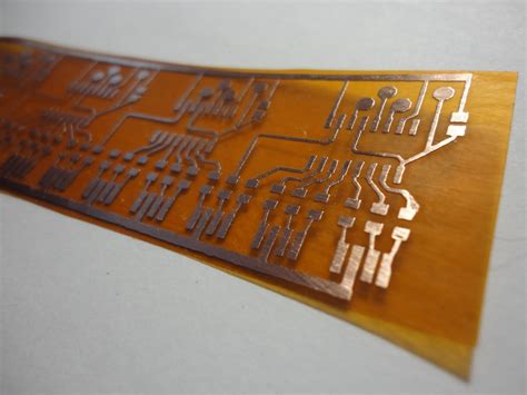
What is Flex PCB?
Flexible printed circuit boards, also known as flex PCBs or flexible circuits, are a type of printed circuit board that consists of a thin, flexible plastic substrate with conductive traces printed on one or both sides. Unlike traditional rigid PCBs, flex PCBs can bend, twist, and fold to fit into tight spaces or conform to unique shapes.
Flex PCBs are made from a variety of materials, including polyimide, polyester, and PEEK (polyetheretherketone). These materials are chosen for their flexibility, durability, and ability to withstand high temperatures and harsh environments.
Advantages of Flex PCBs
Flex PCBs offer several advantages over traditional rigid PCBs:
- Space savings: Flex PCBs can be bent and folded to fit into tight spaces, reducing the overall size of electronic devices.
- Weight reduction: Flex PCBs are typically thinner and lighter than rigid PCBs, making them ideal for portable devices and aerospace applications.
- Improved reliability: By eliminating the need for connectors and wires between rigid PCBs, flex PCBs reduce the risk of connection failures and improve overall system reliability.
- Enhanced design flexibility: Flex PCBs can be designed to conform to unique shapes and curves, enabling more creative and innovative product designs.
- Increased durability: Flex PCBs can withstand vibration, shock, and extreme temperatures better than rigid PCBs, making them suitable for harsh environments.
Types of Flex PCBs
There are several types of flex PCBs, each with its own unique characteristics and applications:
Single-sided Flex PCBs
Single-sided flex PCBs have conductive traces on only one side of the flexible substrate. They are the simplest and most cost-effective type of flex PCB and are often used in applications where high density and complexity are not required.
Double-sided Flex PCBs
Double-sided flex PCBs have conductive traces on both sides of the flexible substrate, allowing for higher density and more complex designs. They are commonly used in applications that require more interconnections and functionality than single-sided flex PCBs can provide.
Multi-layer Flex PCBs
Multi-layer flex PCBs consist of three or more conductive layers separated by insulating layers. They offer the highest density and complexity of all flex PCB Types and are used in applications that require advanced functionality, such as aerospace, medical devices, and high-end consumer electronics.
Rigid-flex PCBs
Rigid-flex PCBs combine the benefits of both rigid and flexible PCBs by incorporating rigid and flexible sections into a single circuit board. The rigid sections provide structural support and accommodate components, while the flexible sections allow the PCB to bend and fold as needed. Rigid-flex PCBs are often used in applications that require a combination of high density, reliability, and flexibility.

Flex PCB Manufacturing Process
The manufacturing process for flex PCBs is similar to that of rigid PCBs, with a few key differences to accommodate the flexible nature of the substrate. The basic steps in the flex PCB manufacturing process are as follows:
-
Design and layout: The first step in the manufacturing process is to design the flex PCB using specialized CAD software. The design must take into account the specific requirements of the application, such as size, shape, and flexibility.
-
Material selection: The appropriate flexible substrate material is selected based on the application’s requirements, such as temperature range, chemical resistance, and flexibility.
-
Printing: The conductive traces are printed onto the flexible substrate using a screen printing or photolithography process. In screen printing, a stencil is used to apply the conductive ink to the substrate. In photolithography, a photosensitive resist is applied to the substrate, exposed to UV light through a mask, and then developed to create the desired pattern.
-
Etching: The unwanted copper is removed from the substrate using a chemical etching process, leaving only the desired conductive traces.
-
Lamination: If the flex PCB is a multi-layer design, the individual layers are laminated together using heat and pressure.
-
Drilling: Holes are drilled through the flex PCB to accommodate components and connectors.
-
Plating: The drilled holes are plated with copper to create electrical connections between layers.
-
Solder mask application: A solder mask is applied to the flex PCB to protect the conductive traces and prevent short circuits.
-
Surface finishing: A surface finish, such as gold or silver, is applied to the exposed copper to prevent oxidation and improve solderability.
-
Cutting and profiling: The flex PCB is cut and profiled to its final shape using a variety of methods, such as die-cutting, laser-cutting, or routing.
-
Testing and inspection: The completed flex PCB is tested and inspected to ensure that it meets the required specifications and performance standards.

Applications of Flex PCBs
Flex PCBs are used in a wide range of industries and applications, including:
-
Consumer electronics: Flex PCBs are commonly used in smartphones, tablets, laptops, and wearable devices to reduce size and weight while improving reliability.
-
Medical devices: Flex PCBs are used in medical devices such as hearing aids, pacemakers, and implantable sensors due to their ability to conform to the body and withstand harsh environments.
-
Aerospace and defense: Flex PCBs are used in aircraft, satellites, and military equipment to reduce weight, save space, and improve reliability in extreme conditions.
-
Automotive: Flex PCBs are used in automotive applications such as dashboard displays, cameras, and sensors to accommodate tight spaces and withstand vibration and temperature fluctuations.
-
Industrial equipment: Flex PCBs are used in industrial equipment such as robots, machine vision systems, and control panels to improve reliability and reduce maintenance costs.

Choosing a Flex PCB Manufacturer
When choosing a flex PCB manufacturer, there are several key factors to consider:
-
Experience and expertise: Look for a manufacturer with extensive experience in producing flex PCBs and a proven track record of delivering high-quality products.
-
Manufacturing capabilities: Ensure that the manufacturer has the necessary equipment and processes in place to produce your specific type of flex PCB, whether it be single-sided, double-sided, multi-layer, or rigid-flex.
-
Quality control: Choose a manufacturer with strict quality control processes in place to ensure that your flex PCBs meet the required specifications and performance standards.
-
Lead times: Consider the manufacturer’s lead times and ability to meet your production schedule.
-
Customer support: Look for a manufacturer with responsive and knowledgeable customer support to help you throughout the design and manufacturing process.
-
Pricing: While price is an important consideration, it should not be the sole determining factor. Look for a manufacturer that offers competitive pricing without compromising on quality or service.
Flex PCB Design Considerations
When designing a flex PCB, there are several key considerations to keep in mind:
-
Bend radius: The bend radius is the minimum radius that the flex PCB can be bent without causing damage. It is important to design the flex PCB with the appropriate bend radius for your application.
-
Conductor width and spacing: The width and spacing of the conductive traces on the flex PCB must be carefully designed to ensure proper signal integrity and prevent short circuits.
-
Stiffener placement: Stiffeners can be added to the flex PCB to provide structural support and prevent damage in areas where the PCB will be bent or flexed repeatedly.
-
Coverlay: A coverlay is a protective layer that is applied to the flex PCB to protect the conductive traces and prevent damage. It is important to choose the appropriate coverlay material and thickness for your application.
-
Connector selection: The type and placement of connectors on the flex PCB must be carefully considered to ensure proper functionality and reliability.
Frequently Asked Questions (FAQ)
1. What is the difference between a flex PCB and a rigid PCB?
A flex PCB is a printed circuit board that is made from a flexible plastic substrate, allowing it to bend and conform to unique shapes. A rigid PCB, on the other hand, is made from a rigid, non-flexible material such as FR-4 and cannot be bent or flexed.
2. What are the advantages of using a flex PCB?
Flex PCBs offer several advantages over rigid PCBs, including space savings, weight reduction, improved reliability, enhanced design flexibility, and increased durability.
3. What industries commonly use flex PCBs?
Flex PCBs are used in a wide range of industries, including consumer electronics, medical devices, aerospace and defense, automotive, and industrial equipment.
4. What factors should I consider when choosing a flex PCB manufacturer?
When choosing a flex PCB manufacturer, consider factors such as experience and expertise, manufacturing capabilities, quality control processes, lead times, customer support, and pricing.
5. What are some key design considerations for flex PCBs?
Key design considerations for flex PCBs include bend radius, conductor width and spacing, stiffener placement, coverlay selection, and connector selection.
Conclusion
Flex PCBs offer a wide range of benefits over traditional rigid PCBs, including space savings, weight reduction, improved reliability, enhanced design flexibility, and increased durability. They are used in a variety of industries and applications, from consumer electronics to medical devices and aerospace equipment.
When designing and manufacturing flex PCBs, it is important to work with an experienced and reputable manufacturer that can provide the necessary expertise, capabilities, and support to ensure a successful outcome. By carefully considering factors such as bend radius, conductor width and spacing, stiffener placement, coverlay selection, and connector selection, designers can create flex PCBs that meet the specific requirements of their application and perform reliably in even the most challenging environments.
| Characteristic | Flex PCB | Rigid PCB |
|---|---|---|
| Material | Flexible plastic substrate | Rigid, non-flexible material (e.g., FR-4) |
| Flexibility | Can bend and conform to unique shapes | Cannot bend or flex |
| Space Savings | Significant space savings due to ability to bend and fold | Limited space savings |
| Weight | Typically thinner and lighter than rigid PCBs | Heavier than flex PCBs |
| Reliability | Improved reliability due to elimination of connectors and wires | Potential for connection failures due to connectors and wires |
| Design Flexibility | Enhanced design flexibility due to ability to conform to unique shapes and curves | Limited design flexibility |
| Durability | Increased durability in harsh environments and conditions | Limited durability in harsh environments and conditions |