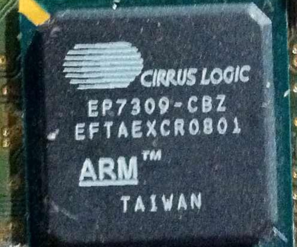
Overview of the 74HC238 IC
The 74HC238 is an 8-line 3-to-8 line decoder IC chip produced by various manufacturers. It takes a 3-bit binary input and converts it to 1-of-8 active low outputs. This allows it to decode a 3-bit binary number into one of eight unique output lines. The 74HC238 contains active high enables and is commonly used in digital logic circuits.
Key Features of the 74HC238
- Decodes 3-bit binary input to 1-of-8 active low outputs
- Active high enable pins (E1, E2, E3)
- Output lines sink up to 20mA
- Wide operating voltage range of 2-6V
- High noise immunity
- High speed CMOS technology
Steps to Crack the 74HC238 Chip
Cracking the 74HC238 involves reverse engineering the internal circuitry and logic gates. This allows recreating the functional behavior and enables using the chip in custom circuits. Here are the key steps:
1. Desolder the Chip from the PCB
- Use a desoldering pump or solder wick to remove the 74HC238 chip from the PCB it’s mounted on.
- Gently heat each pin while applying vacuum or wick to remove all solder.
- Once all pins are desoldered, use tweezers to remove the chip.
2. Clean the Pins
- Use isopropyl alcohol and a toothbrush to gently clean off any residual solder or flux from the pins.
- Ensure no shorts between any pins before proceeding.
3. Trace the Internal Connections
- Use a multimeter in continuity test mode to trace connections between the various pins.
- Probe different pin combinations to map the internal gates and circuits.
- Draw a pinout diagram detailing your findings.
4. Identify the Internal Logic Gates
- The chip will contain NAND, NOR, and inverter CMOS logic gates.
- Measure pin HIGH/LOW levels to deduce gate types and inputs/outputs.
- Consult the transistor-level schematic [1] to verify your logic gate diagram.
5. Recreate the Circuit Schematic
- Use your pinout diagram and logic gate findings to draw the complete internal schematic.
- Verify expected function table matches datasheet specifications [2].
- The 74HC238 schematic is now reverse engineered!
Applications and Use Cases
With the internal schematic recreated, the 74HC238 can now be used in custom circuits and applications:
- Digital logic breadboards and prototypes
- Custom decoders for memory addressing
- Segment selection in displays and 7-segment decoders
- Communication bus selection and multiplexing
- Analog switch control and input selection
The cracked 74HC238 provides a versatile 3-to-8 line decoder for projects that require binary-coded decimal conversion.
Frequently Asked Questions
What tools do I need to crack the 74HC238?
You’ll need basic electronic tools like a soldering iron, desoldering pump, tweezers, multimeter, jumper wires, breadboard, etc. An oscilloscope can also help analyze signals.
How can I verify my logic diagram is correct?
Thoroughly test with different input combinations and verify the outputs match the expected function table. Consult the datasheet truth table and transistor schematic.
Is it legal to reverse engineer chips like the 74HC238?
For personal education and non-commercial use, reverse engineering chips is generally legal under fair use exemptions. However, check your specific country’s laws.
What if I accidentally damage the chip while cracking it?
These chips can be purchased very cheaply, so you can always start over with a new one. Work slowly and carefully while reverse engineering.
Can the cracked 74HC238 be used in commercial products?
No, the reverse engineered chip would likely violate patents and copyrights. Only use cracked chips for personal education/hobbyists purposes.
References
[1] 74HC238 Transistor-Level Schematic
[2] 74HC238 Datasheet
