Judy@4pcba.com
7:30 AM - 7:30 PM
Monday to Saturday

Archive: March 13, 2024

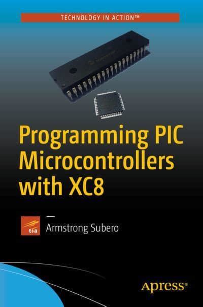
Which software is used to program PIC microcontroller?

What is a PIC microcontroller?

Before we dive into the software options, let’s first understand what a PIC microcontroller is. PIC stands for “Peripheral Interface Controller” and refers to a family of microcontrollers developed by Microchip Technology. These microcontrollers are designed for embedded applications and offer a wide range of features such as:

  • Low power consumption
  • High performance
  • Integrated peripherals (e.g. ADC, PWM, UART)
  • In-circuit programming and debugging

PIC microcontrollers come in various sizes and configurations, ranging from 8-pin to 100-pin packages with different memory sizes and peripheral options. Some popular PIC microcontroller families include:

  • PIC10
  • PIC12
  • PIC16
  • PIC18
  • PIC24
  • dsPIC

PIC Programming software options

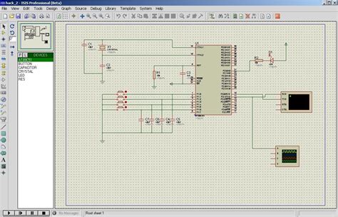
To program a PIC microcontroller, you need to use an Integrated Development Environment (IDE) that supports the specific device you are using. An IDE is a software application that provides a comprehensive environment for writing, compiling, and debugging code. Here are some of the most popular PIC programming software options:

MPLAB X IDE

MPLAB X IDE is the official IDE provided by Microchip for programming PIC microcontrollers. It is a free, cross-platform software that supports all PIC devices and offers a wide range of features such as:

  • Syntax highlighting and code completion
  • Integrated debugger and programmer
  • Code profiling and optimization
  • Plugin support for third-party tools

MPLAB X IDE uses the MPLAB XC compilers, which are available in both free and paid versions. The free version has some limitations in terms of optimization and code size, while the paid version offers full optimization and support.

To get started with MPLAB X IDE, you need to:

  1. Download and install MPLAB X IDE from the Microchip website
  2. Select your PIC device and compiler
  3. Write your code in C or assembly language
  4. Compile and debug your code using the integrated tools
  5. Upload your code to the PIC microcontroller using a programmer (e.g. PICkit, ICD)

MPLAB X IDE is a powerful and versatile tool for PIC programming, but it can have a steep learning curve for beginners.

MPLAB IPE

MPLAB IPE (Integrated Programming Environment) is a simplified version of MPLAB X IDE that focuses on programming and debugging PIC microcontrollers. It is a free, standalone application that supports most PIC devices and offers a user-friendly interface for quick programming tasks.

MPLAB IPE includes features such as:

  • Simplified project creation and management
  • Integrated programmer and debugger support
  • Automatic device detection and configuration
  • Firmware updates for programmers and debuggers

To use MPLAB IPE, you need to:

  1. Download and install MPLAB IPE from the Microchip website
  2. Connect your PIC microcontroller to the programmer or debugger
  3. Select your device and configure the programming settings
  4. Load your hex file and program the device

MPLAB IPE is a great choice for simple programming tasks or for beginners who want a more straightforward interface.

PICkit

PICkit is a series of low-cost programmers and debuggers for PIC microcontrollers. These tools are designed to work with MPLAB X IDE and MPLAB IPE and offer features such as:

  • In-circuit programming and debugging
  • Firmware updates for PIC microcontrollers
  • Breakpoint and single-step debugging
  • Real-time variable monitoring

The latest version of PICkit is PICkit 4, which supports most PIC devices and offers faster programming speeds and advanced debugging features. To use PICkit with MPLAB X IDE or MPLAB IPE, you need to:

  1. Connect PICkit to your computer and PIC microcontroller
  2. Select PICkit as your programmer or debugger in the IDE
  3. Configure the programming settings and load your code
  4. Program or debug your code using the integrated tools

PICkit is a cost-effective and reliable tool for PIC programming and debugging.

mikroC for PIC

mikroC for PIC is a commercial IDE developed by mikroElektronika for programming PIC microcontrollers. It is a powerful and user-friendly software that offers features such as:

  • Simplified syntax and code examples
  • Integrated debugger and programmer support
  • Libraries and tools for common peripherals (e.g. LCD, EEPROM)
  • Automatic code generation and optimization

mikroC for PIC uses a custom compiler that is optimized for PIC devices and offers faster compilation times and smaller code size compared to other compilers. However, it is a paid software and requires a license for commercial use.

To use mikroC for PIC, you need to:

  1. Download and install mikroC for PIC from the mikroElektronika website
  2. Select your PIC device and configure the project settings
  3. Write your code using the simplified syntax and libraries
  4. Compile and debug your code using the integrated tools
  5. Upload your code to the PIC microcontroller using a supported programmer

mikroC for PIC is a great choice for beginners who want a simplified and intuitive interface for PIC programming.

CCS PIC C Compiler

CCS PIC C Compiler is another commercial IDE for programming PIC microcontrollers using the C language. It is a powerful and feature-rich software that offers:

  • ANSI C compiler with PIC-specific extensions
  • Integrated debugger and programmer support
  • Libraries and examples for common applications
  • Automatic code generation and optimization

CCS PIC C Compiler is known for its efficient and optimized code generation, which can result in faster and smaller code compared to other compilers. However, it is a paid software and requires a license for commercial use.

To use CCS PIC C Compiler, you need to:

  1. Download and install CCS PIC C Compiler from the CCS website
  2. Select your PIC device and configure the project settings
  3. Write your code using the ANSI C syntax and PIC-specific extensions
  4. Compile and debug your code using the integrated tools
  5. Upload your code to the PIC microcontroller using a supported programmer

CCS PIC C Compiler is a great choice for experienced embedded programmers who want a powerful and efficient tool for PIC programming.
Comparison of PIC programming software

Software Vendor License Supported Devices Features
MPLAB X IDE Microchip Free All PIC devices Syntax highlighting, integrated debugger, code optimization
MPLAB IPE Microchip Free Most PIC devices Simplified interface, automatic device detection
PICkit Microchip Paid Most PIC devices In-circuit programming and debugging, firmware updates
mikroC for PIC mikroElektronika Paid Most PIC devices Simplified syntax, integrated debugger, libraries and tools
CCS PIC C Compiler CCS Paid Most PIC devices ANSI C compiler, integrated debugger, efficient code generation

Choosing the right PIC programming software depends on your specific needs and preferences. If you are a beginner, you may prefer a simplified interface like MPLAB IPE or mikroC for PIC. If you are an experienced programmer, you may prefer a more powerful and feature-rich IDE like MPLAB X IDE or CCS PIC C Compiler. Ultimately, the best software is the one that allows you to write, compile, and debug your code efficiently and effectively.

FAQ

What is the best PIC programming software for beginners?

For beginners, MPLAB IPE or mikroC for PIC are good choices due to their simplified interfaces and easy-to-use features. MPLAB IPE is a free software provided by Microchip, while mikroC for PIC is a paid software with a more intuitive syntax and built-in libraries.

Can I use Arduino IDE to program PIC microcontrollers?

No, Arduino IDE is designed specifically for Arduino boards and does not support PIC microcontrollers. To program PIC microcontrollers, you need to use a specialized IDE like MPLAB X IDE, MPLAB IPE, mikroC for PIC, or CCS PIC C Compiler.

Do I need a programmer to upload code to a PIC microcontroller?

Yes, you need a programmer or debugger to upload code to a PIC microcontroller. Some popular programmers include PICkit, ICD, and SNAP. These programmers connect to your computer via USB and allow you to transfer your code to the PIC device.

Can I use C++ to program PIC microcontrollers?

While most PIC programming software supports C language, some also support C++ with limitations. For example, MPLAB XC compilers support a subset of C++ features, while mikroC for PIC supports C++ with some modifications. However, using C++ for PIC programming may result in larger code size and slower performance compared to using C.

How do I choose the right PIC microcontroller for my project?

Choosing the right PIC microcontroller depends on your project requirements such as:

  • Number of I/O pins
  • Memory size
  • Processing speed
  • Peripheral options
  • Power consumption

You can use Microchip’s product selector tool or consult with their technical support to find the best PIC device for your needs. It’s also important to consider the availability and cost of the device, as well as the compatibility with your preferred programming software.
Conclusion

In this article, we explored the various software options available for PIC programming, including MPLAB X IDE, MPLAB IPE, PICkit, mikroC for PIC, and CCS PIC C Compiler. We also compared the features and benefits of each software and provided guidance on how to choose the right one for your needs.

PIC microcontrollers are a versatile and powerful platform for embedded systems and electronic projects. By using the right programming software and tools, you can unleash the full potential of these devices and create innovative solutions for a wide range of applications.

Whether you are a beginner or an experienced programmer, there is a PIC programming software that can meet your needs and help you bring your ideas to life. So, choose your software wisely, write your code carefully, and happy programming!
How do you identify an IC problem?

Introduction to IC Problem Identification

Integrated circuits (ICs) are essential components in modern electronic devices, ranging from smartphones and computers to industrial machinery and medical equipment. However, like any other electronic component, ICs can experience problems that affect the overall performance and reliability of the device. Identifying IC problems is crucial for troubleshooting, repairing, and maintaining electronic systems. In this article, we will explore various methods and techniques for identifying IC problems, helping you diagnose and resolve issues efficiently.

Common IC Problems

Before diving into the identification process, let’s discuss some common IC problems that you may encounter:

1. Open Circuits

An open circuit occurs when there is a break in the electrical path within the IC, preventing current from flowing through the affected pin or internal component. This can be caused by manufacturing defects, physical damage, or excessive stress on the IC.

2. Short Circuits

A short circuit happens when two or more pins or internal components of an IC are unintentionally connected, allowing current to flow through an unintended path. Short circuits can be caused by manufacturing defects, electrostatic discharge (ESD), or physical damage to the IC.

3. Parametric Failures

Parametric failures occur when an IC’s electrical characteristics, such as voltage, current, or timing, fall outside the specified range. These failures can be caused by manufacturing variations, environmental factors, or aging of the IC.

4. Functional Failures

Functional failures happen when an IC does not perform its intended function, even though its electrical characteristics may be within the specified range. These failures can be caused by design errors, manufacturing defects, or incompatibility with other components in the system.

Visual Inspection Techniques

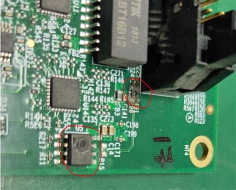
Visual inspection is the first step in identifying IC problems. By examining the IC and its surrounding components, you can often spot signs of damage or abnormalities that may indicate a problem.

1. Inspection under Magnification

Using a magnifying glass or a microscope, carefully examine the IC for any visible signs of damage, such as:

  • Cracks or chips in the IC package
  • Bent or broken pins
  • Discoloration or charring of the IC surface
  • Foreign material or debris on the IC or its pins

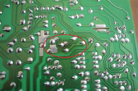
2. Inspection of Solder Joints

Check the solder joints that connect the IC to the printed circuit board (PCB). Look for any signs of poor soldering, such as:

  • Cold solder joints (dull, grainy appearance)
  • Excessive or insufficient solder
  • Solder bridges between pins
  • Lifted or misaligned IC pins

3. Thermal Imaging

Thermal imaging cameras can help identify ICs that are generating excessive heat, which may indicate a problem. Look for hot spots on the IC or surrounding components that deviate significantly from the normal thermal profile of the system.

Electrical Testing Methods

Electrical testing involves measuring the IC’s electrical characteristics and comparing them to the expected values specified in the datasheet. This helps identify parametric and functional failures.

1. Continuity Testing

Use a multimeter to test the continuity between the IC’s pins and the PCB traces. This helps identify open circuits and ensures proper connections between the IC and other components.

2. Voltage and Current Measurements

Measure the voltage and current at the IC’s pins and compare them to the expected values. Pay attention to the supply voltage, input/output voltages, and current consumption. Deviations from the specified ranges may indicate a problem with the IC or the surrounding circuitry.

3. Oscilloscope Measurements

An oscilloscope allows you to visualize and analyze the waveforms at the IC’s pins. This is particularly useful for identifying timing-related issues, such as:

  • Signal integrity problems (e.g., ringing, overshoot, undershoot)
  • Incorrect timing or frequency of clock signals
  • Abnormal waveform shapes or amplitudes

4. In-Circuit Testing

In-circuit testing involves using a specialized test fixture or probe to access the IC’s pins while it is still soldered to the PCB. This allows you to perform more comprehensive tests, such as:

  • Functional testing of the IC’s inputs and outputs
  • Boundary scan testing (for ICs with built-in test features)
  • Parametric testing of the IC’s electrical characteristics

Comparison with Known Good Circuit

Comparing the suspect IC’s behavior and electrical characteristics with a known good circuit can help identify problems. This technique is particularly useful when you have access to a functioning system that uses the same type of IC.

1. Side-by-Side Comparison

Set up the suspect and known good systems side by side and compare their behavior. Look for any differences in functionality, performance, or error messages.

2. Waveform Comparison

Using an oscilloscope, capture the waveforms at the IC’s pins on both the suspect and known good systems. Compare the waveforms for any discrepancies in shape, amplitude, or timing.

3. Voltage and Current Comparison

Measure the voltage and current at the IC’s pins on both systems and compare the values. Any significant differences may indicate a problem with the suspect IC or its surrounding circuitry.

Failure Analysis Techniques

When visual inspection and electrical testing do not provide conclusive results, more advanced failure analysis techniques may be necessary. These techniques typically require specialized equipment and expertise.

1. X-Ray Imaging

X-ray imaging allows you to see inside the IC package without physically opening it. This technique can reveal internal defects, such as:

  • Cracks in the die or substrate
  • Voids or delamination in the die attach or wire bonds
  • Foreign material or debris inside the package

2. Decapsulation

Decapsulation involves removing the IC package to expose the die and internal components. This allows for direct visual inspection and probing of the die. However, decapsulation is a destructive process and should only be performed when other methods have been exhausted.

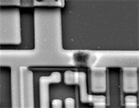
3. Scanning Electron Microscopy (SEM)

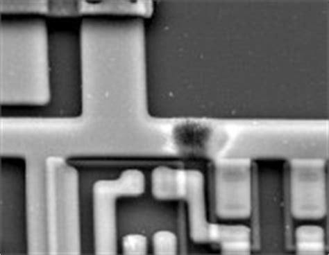
SEM provides high-resolution images of the IC’s surface and internal structures. This technique can reveal microscopic defects, such as:

  • Cracks or voids in the metal layers
  • Electromigration or corrosion of the interconnects
  • Gate oxide damage or breakdown

4. Focused Ion Beam (FIB)

FIB allows for precise milling and imaging of the IC’s internal structures. This technique can be used to:

  • Cross-section specific areas of the die for analysis
  • Modify or repair the IC’s internal connections
  • Extract samples for further analysis (e.g., transmission electron microscopy)

Frequently Asked Questions (FAQ)

1. What are the most common causes of IC failures?

The most common causes of IC failures include:

  • Electrostatic discharge (ESD)
  • Overheating or thermal stress
  • Physical damage (e.g., mechanical shock, vibration)
  • Manufacturing defects
  • Aging or wear-out of the IC

2. Can all IC problems be identified through visual inspection?

No, not all IC problems can be identified through visual inspection alone. Some issues, such as parametric failures or internal defects, may require electrical testing or advanced failure analysis techniques to detect.

3. What safety precautions should I take when handling ICs?

When handling ICs, always take the following safety precautions:

  • Use ESD protection (e.g., grounded wrist strap, ESD-safe work surface)
  • Handle ICs by their edges or packaging, avoiding contact with the pins
  • Avoid exposing ICs to extreme temperatures, humidity, or mechanical stress
  • Follow proper storage and handling procedures as specified by the manufacturer

4. Can I replace a faulty IC with a different part number?

In general, it is not recommended to replace a faulty IC with a different part number unless the replacement is specified as a compatible substitute by the manufacturer. Different part numbers may have variations in electrical characteristics, pinout, or functionality that could affect the system’s performance.

5. When should I seek professional help for identifying IC problems?

If you have exhausted all available troubleshooting methods and are still unable to identify the IC problem, or if the issue requires specialized equipment or expertise, it is advisable to seek professional help from an experienced electronIC repair service or the IC manufacturer’s support team.

Conclusion

Identifying IC problems is a critical skill for anyone involved in the design, maintenance, or repair of electronic systems. By combining visual inspection, electrical testing, and advanced failure analysis techniques, you can effectively diagnose and resolve IC issues. Remember to approach the problem systematically, starting with non-destructive methods and progressively moving towards more invasive techniques as needed. With practice and experience, you will develop a keen eye for spotting IC problems and efficiently troubleshooting electronic systems.

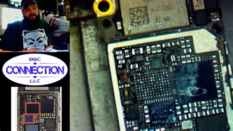
What causes IC damage on iPhone?

Understanding IC damage on iPhones

Integrated circuits (ICs) are crucial components in modern electronic devices, including iPhones. These tiny chips are responsible for processing and controlling various functions within the device. However, ICs are susceptible to damage, which can lead to malfunctions or complete failure of the iPhone. In this article, we will explore the common causes of IC damage on iPhones and how to prevent them.

What are integrated circuits (ICs)?

Integrated circuits, also known as microchips, are miniaturized electronic circuits that consist of transistors, resistors, capacitors, and other components. These components are fabricated onto a single semiconductor substrate, typically made of silicon. ICs are designed to perform specific functions within electronic devices, such as processing data, controlling power, or managing communication between components.

The role of ICs in iPhones

In iPhones, ICs play a vital role in enabling various features and functions. Some of the essential ICs found in iPhones include:

  1. A-series processor: This is the main processing unit of the iPhone, responsible for running applications and managing overall device performance.
  2. Baseband processor: This IC handles cellular communication, enabling the iPhone to connect to mobile networks for calls, texts, and data.
  3. Power management IC (PMIC): This chip manages the iPhone’s power distribution, ensuring that each component receives the appropriate voltage and current.
  4. NFC controller: This IC enables Near Field Communication (NFC) functionality, which is used for features like Apple Pay.

Common causes of IC damage on iPhones

1. Physical damage

One of the most common causes of IC damage on iPhones is physical damage. This can occur due to various reasons, such as:

Drops and impacts

When an iPhone is dropped or subjected to a strong impact, the sudden force can cause the delicate ICs to crack, dislodge, or become disconnected from the circuit board. Even if the external casing of the iPhone appears undamaged, internal components like ICs can still be affected.

Bending and flexing

iPhones are designed to be slim and portable, but this also makes them susceptible to bending and flexing. When an iPhone is subjected to excessive bending or flexing, the circuit board and its components, including ICs, can be strained and damaged.

Pressure and compression

Applying excessive pressure or compression to an iPhone can also lead to IC damage. This can happen when the device is sat on, stepped on, or subjected to a heavy object.

2. Liquid damage

Another common cause of IC damage on iPhones is liquid damage. When liquid comes into contact with the iPhone’s internal components, it can cause short-circuits, corrosion, and oxidation, which can lead to IC Failure.

Water exposure

iPhones are resistant to water to a certain degree, but prolonged exposure or submersion can still cause damage. When water seeps into the device, it can reach the ICs and cause short-circuits or corrosion.

Other liquids

In addition to water, other liquids like soda, coffee, or chemicals can also damage ICs if they come into contact with the iPhone’s internal components. These liquids can be more corrosive than water and cause more severe damage.

3. Overheating

ICs generate heat during operation, and iPhones are designed to dissipate this heat effectively. However, if the device is subjected to excessive heat or if the heat dissipation mechanisms fail, it can lead to IC damage.

Prolonged exposure to high temperatures

When an iPhone is left in a hot environment, such as direct sunlight or inside a parked car on a hot day, the internal temperature can rise to dangerous levels. This can cause the ICs to overheat and suffer damage.

Intensive use

Running demanding applications or games for extended periods can cause the iPhone’s ICs to generate more heat than usual. If the device is unable to dissipate this heat effectively, it can lead to IC damage.

Charging issues

Using unauthorized or faulty chargers can cause the iPhone to overheat during charging. This can damage the ICs responsible for power management and other functions.

4. Electrostatic discharge (ESD)

Electrostatic discharge (ESD) occurs when a sudden flow of electricity passes through the iPhone, often due to static buildup on the user or the environment. This can cause damage to the sensitive ICs within the device.

Handling the iPhone without proper grounding

When handling an iPhone, it is essential to ensure that you are properly grounded to avoid transferring static electricity to the device. This is particularly important when replacing or repairing internal components.

Exposing the iPhone to static-prone environments

Some environments, such as carpeted rooms or areas with low humidity, are more prone to static buildup. Using an iPhone in these environments without proper precautions can increase the risk of ESD damage.

5. Manufacturing defects

In rare cases, IC damage can be caused by manufacturing defects. These defects can be due to issues in the fabrication process or the use of substandard materials.

Faulty IC fabrication

If an IC is not fabricated correctly, it may have inherent weaknesses or vulnerabilities that can lead to premature failure or damage.

Substandard materials

Using substandard materials in the production of ICs can also lead to damage. These materials may not have the required properties to withstand the normal operating conditions of the iPhone.

Symptoms of IC damage on iPhones

When an iPhone suffers from IC damage, it can exhibit various symptoms depending on the affected chip and the extent of the damage. Some common symptoms include:

  1. No power: If the power management IC is damaged, the iPhone may not turn on or may experience sudden shutdowns.
  2. Display issues: Damage to the display driver IC can cause screen abnormalities, such as flickering, distortion, or a completely non-functional display.
  3. Touch problems: If the touch controller IC is affected, the iPhone may experience unresponsive or erratic touch input.
  4. Connectivity issues: A damaged baseband processor can lead to problems with cellular connectivity, such as dropped calls, poor reception, or the inability to connect to mobile networks.
  5. Battery problems: IC damage can also cause battery issues, such as rapid draining or the inability to charge.
Symptom Potential Cause
No power Power management IC damage
Display issues Display driver IC damage
Touch problems Touch controller IC damage
Connectivity issues Baseband processor damage
Battery problems Power management IC or Charging IC damage

Preventing IC damage on iPhones

To minimize the risk of IC damage on your iPhone, follow these preventive measures:

  1. Use a protective case: A high-quality case can help absorb impacts and prevent physical damage to your iPhone.
  2. Avoid exposing your iPhone to liquids: Keep your device away from water and other liquids. If your iPhone gets wet, turn it off immediately and allow it to dry thoroughly before attempting to use it again.
  3. Maintain a safe operating temperature: Avoid leaving your iPhone in hot environments and ensure proper ventilation during intensive use.
  4. Use authorized chargers and accessories: Only use chargers and accessories that are certified by Apple or reputable third-party manufacturers to avoid overheating and ESD issues.
  5. Handle your iPhone with care: Be mindful of how you handle your device, especially when replacing or repairing internal components. Always ensure proper grounding to prevent ESD damage.

Frequently Asked Questions (FAQ)

1. Can IC damage be repaired on an iPhone?

In some cases, IC damage can be repaired by skilled technicians using specialized equipment. However, the success of the repair depends on the extent of the damage and the specific IC affected. In severe cases, the Damaged IC may need to be replaced entirely.

2. Will Apple repair an iPhone with IC damage under warranty?

Apple’s warranty typically does not cover damage caused by accidents, liquid exposure, or unauthorized modifications. If the IC damage is determined to be caused by such factors, Apple may not repair the device under warranty. However, if the damage is due to a manufacturing defect, it may be covered.

3. How much does it cost to repair IC damage on an iPhone?

The cost of repairing IC damage on an iPhone can vary depending on the specific issue, the iPhone model, and the repair provider. In general, IC Repairs can be more expensive than other types of repairs due to the complexity and precision required. It is best to consult with a reputable repair service for an accurate estimate.

4. Can I prevent IC damage by using a waterproof case?

While a waterproof case can provide some protection against liquid damage, it is not a foolproof solution. Waterproof cases can still allow liquid to enter if they are not properly sealed or if they sustain damage. It is always best to avoid exposing your iPhone to liquids altogether.

5. How can I tell if my iPhone has IC damage?

If your iPhone exhibits any of the symptoms mentioned earlier, such as power issues, display problems, touch irregularities, connectivity issues, or battery problems, it may have IC damage. However, these symptoms can also be caused by other factors. To determine if IC damage is the culprit, it is best to have your iPhone diagnosed by a professional technician.

Conclusion

IC damage on iPhones can be caused by various factors, including physical damage, liquid exposure, overheating, electrostatic discharge, and manufacturing defects. By understanding these causes and taking appropriate preventive measures, you can help protect your iPhone from IC damage. If you suspect that your iPhone has suffered IC damage, it is essential to have it diagnosed and repaired by a skilled technician to prevent further damage and restore proper functionality.

What happens if IC is damaged?

Understanding Integrated Circuits (ICs) and Their Importance

An integrated circuit (IC) is a miniaturized electronic circuit that consists of numerous components such as transistors, resistors, capacitors, and diodes, all fabricated on a single semiconductor substrate. ICs have revolutionized the electronics industry by enabling the development of compact, efficient, and reliable electronic devices. They are found in a wide range of applications, from simple consumer electronics to complex industrial systems and aerospace technology.

Types of Integrated Circuits

There are several types of integrated circuits, each designed for specific purposes:

  1. Analog ICs: These ICs process continuous signals and are used in applications such as amplifiers, voltage regulators, and sensors.

  2. Digital ICs: These ICs process discrete signals (1s and 0s) and are used in digital logic circuits, microprocessors, and memory devices.

  3. Mixed-signal ICs: These ICs combine both analog and digital circuits on a single chip and are used in applications such as data converters and communication systems.

The Role of ICs in Modern Electronics

ICs have become the backbone of modern electronics due to their numerous advantages:

  1. Miniaturization: ICs allow for the integration of thousands or even millions of components on a single chip, reducing the size and weight of electronic devices.

  2. Increased reliability: By minimizing the number of discrete components and interconnections, ICs reduce the chances of component failure and improve overall system reliability.

  3. Enhanced performance: ICs enable faster signal processing, lower power consumption, and improved noise immunity compared to discrete component circuits.

  4. Cost-effectiveness: Mass production of ICs has made them more affordable, enabling the widespread adoption of electronic devices in various industries.

Common Causes of IC damage

Despite their numerous benefits, integrated circuits are susceptible to various types of damage that can affect their performance or render them non-functional. Some common causes of IC damage include:

Electrostatic Discharge (ESD)

Electrostatic discharge (ESD) is a sudden flow of electricity between two electrically charged objects. ICs are particularly sensitive to ESD, as the high voltage and current associated with an ESD event can damage the delicate internal components of the chip.

ESD can occur due to various reasons:

  1. Human body model (HBM): This occurs when a charged person touches an IC, causing a discharge through the chip.

  2. Machine model (MM): This happens when a charged machine or tool comes in contact with an IC.

  3. Charged device model (CDM): This occurs when an IC itself becomes charged and discharges to a grounded surface.

To prevent ESD damage, it is essential to implement proper ESD protection measures, such as:

  • Using ESD-safe packaging materials and handling procedures
  • Wearing ESD-safe clothing and using grounded wrist straps when handling ICs
  • Maintaining a static-free work environment

Overcurrent and Overvoltage

ICs are designed to operate within specific current and voltage ranges. Exposing them to excessive current or voltage can cause permanent damage to the internal components.

Overcurrent can occur due to:

  1. Short circuits: When a low-resistance path forms between the power supply and ground, leading to a high current flow through the IC.

  2. Incorrect power supply connections: Connecting the IC to a power supply with a higher voltage than its maximum rating can cause overcurrent.

Overvoltage can happen when:

  1. Power supply fluctuations: Sudden spikes or surges in the power supply voltage can exceed the IC’s maximum voltage rating.

  2. Incorrect power supply connections: Connecting the IC to a power supply with a higher voltage than its maximum rating can cause overvoltage.

To prevent overcurrent and overvoltage damage, it is crucial to:

  • Use current-limiting resistors and fuses in series with the IC
  • Ensure proper power supply connections and regulation
  • Implement overvoltage protection circuits, such as transient voltage suppressors (TVS) or Zener diodes

Thermal Stress

ICs generate heat during operation due to the power dissipation of the internal components. Excessive heat can cause thermal stress, leading to performance degradation or permanent damage.

Thermal stress can occur due to:

  1. Inadequate heat dissipation: Poor thermal management, such as insufficient heatsinking or airflow, can cause the IC to overheat.

  2. High ambient temperatures: Operating the IC in environments with high ambient temperatures can exacerbate the heat generation and dissipation challenges.

  3. Power overload: Drawing excessive current through the IC can lead to increased power dissipation and heat generation.

To mitigate thermal stress, it is important to:

  • Use appropriate heatsinks and thermal management techniques
  • Ensure adequate airflow and ventilation around the IC
  • Operate the IC within its specified power and temperature ratings

Mechanical Damage

ICs are delicate components that can be damaged by mechanical stress, such as shock, vibration, or physical impact.

Mechanical damage can occur due to:

  1. Improper handling: Dropping or mishandling the IC during assembly or transportation can cause internal damage or lead to broken pins.

  2. PCB flexing: Excessive bending or flexing of the printed circuit board (PCB) on which the IC is mounted can cause mechanical stress on the chip.

  3. Inadequate mounting: Poor soldering or insufficient mechanical support can lead to the IC becoming loose or detached from the PCB.

To prevent mechanical damage, it is essential to:

  • Handle ICs with care, using proper tools and techniques
  • Design PCBs with appropriate mechanical support and strain relief
  • Use robust packaging and transportation methods

Symptoms and Effects of IC Damage

When an IC is damaged, it can exhibit various symptoms and effects that impact the performance and functionality of the electronic device. Some common symptoms and effects of IC damage include:

Partial or Complete Malfunction

Depending on the extent and nature of the damage, an IC may experience partial or complete malfunction. Partial malfunction can manifest as:

  1. Degraded performance: The IC may still function, but with reduced accuracy, speed, or efficiency.

  2. Intermittent operation: The IC may work inconsistently, experiencing random failures or glitches.

Complete malfunction occurs when the IC stops functioning altogether, leading to a non-operational device.

Increased Power Consumption

Damaged ICs may draw excessive current, leading to increased power consumption. This can be caused by:

  1. Short circuits: Internal short circuits can create low-resistance paths, causing high current flow and power dissipation.

  2. Leakage currents: Damage to the IC’s insulation or passivation layers can result in increased leakage currents, contributing to higher power consumption.

Increased power consumption can lead to reduced battery life in portable devices, overheating, and potential damage to other components.

Erratic or Unexpected Behavior

A damaged IC may exhibit erratic or unexpected behavior, such as:

  1. Incorrect output: The IC may generate incorrect or inconsistent output signals, leading to faulty data processing or control.

  2. Unintended activation: The IC may trigger unintended functions or activate at inappropriate times.

  3. Noise or interference: Damaged ICs can introduce noise or interference into the system, affecting the performance of other components.

Erratic behavior can be difficult to diagnose and may require extensive testing and troubleshooting to identify the root cause.

Physical Damage

In some cases, IC damage may be visible through physical inspection. Common signs of physical damage include:

  1. Cracks or fractures: Impact or mechanical stress can cause cracks or fractures in the IC package or die.

  2. Burn marks: Overcurrent or overvoltage events can leave visible burn marks on the IC package or surrounding components.

  3. Deformed or broken pins: Mishandling or improper insertion can result in bent, deformed, or broken pins on the IC package.

Physical damage is often irreversible and requires the replacement of the affected IC.

Troubleshooting and Repairing Damaged ICs

When an IC is suspected to be damaged, troubleshooting and repair efforts can be undertaken to identify the problem and potentially restore functionality. However, it is important to note that in many cases, damaged ICs may need to be replaced entirely.

Visual Inspection

The first step in troubleshooting a damaged IC is to perform a visual inspection. This involves:

  1. Checking for physical damage: Look for cracks, fractures, burn marks, or deformed pins on the IC package.

  2. Inspecting solder joints: Check the solder joints connecting the IC to the PCB for any signs of damage, corrosion, or poor connection.

  3. Examining surrounding components: Look for any damage or anomalies in the components and traces near the IC.

Visual inspection can help identify obvious signs of damage and guide further troubleshooting efforts.

Continuity and Resistance Tests

Continuity and resistance tests can be performed using a multimeter to check for short circuits, open circuits, or abnormal resistance values within the IC.

  1. Continuity test: This test checks for the presence of a conductive path between two points. It can help identify short circuits or open circuits within the IC or its connections.

  2. Resistance test: This test measures the resistance between two points. Abnormal resistance values can indicate damage to the IC’s internal components or connections.

These tests can provide valuable information about the IC’s internal state and help pinpoint the location of the damage.

Functional Testing

Functional testing involves subjecting the IC to its intended operating conditions and evaluating its performance. This can be done using specialized test equipment or by incorporating the IC into a test circuit.

  1. Bench testing: This involves testing the IC on a test bench using signal generators, oscilloscopes, and other test equipment to assess its functionality.

  2. In-circuit testing: This involves testing the IC while it is installed in the actual circuit, allowing for the evaluation of its performance under real-world conditions.

Functional testing can help identify performance issues, erratic behavior, or complete malfunction of the IC.

Replacement

In many cases, particularly with severe damage, the most practical solution is to replace the damaged IC with a new one. When replacing an IC:

  1. Ensure compatibility: Select a replacement IC that is compatible with the original in terms of package type, pin configuration, and functionality.

  2. Use proper tools and techniques: Use appropriate soldering tools and follow best practices for IC removal and installation to avoid further damage.

  3. Verify functionality: After replacing the IC, perform thorough testing to ensure that the device functions as intended.

Replacing a damaged IC can be a cost-effective and time-efficient solution, especially when troubleshooting and repair efforts prove challenging or unsuccessful.

Prevention and Best Practices

Preventing IC damage is crucial to ensure the reliability and longevity of electronic devices. Some best practices to minimize the risk of IC damage include:

  1. Proper handling: Always handle ICs with care, using ESD-safe tools and procedures. Avoid touching the pins or exposed surfaces of the IC.

  2. ESD protection: Implement ESD protection measures, such as grounded workstations, ESD-safe packaging, and personal grounding equipment.

  3. Correct power supply: Ensure that the IC is powered with the correct voltage and current levels, as specified in its datasheet. Use voltage regulators and current-limiting devices where necessary.

  4. Thermal management: Provide adequate heat dissipation through proper PCB design, heatsinking, and airflow management. Operate ICs within their specified temperature ranges.

  5. Mechanical protection: Design PCBs with appropriate mechanical support and strain relief for ICs. Use robust packaging and transportation methods to minimize mechanical stress.

  6. Quality control: Implement strict quality control measures during the manufacturing and assembly processes to identify and rectify potential issues before they lead to IC damage.

  7. Regular maintenance: Perform regular inspections and maintenance of electronic devices to identify and address any signs of IC degradation or damage promptly.

By following these best practices and taking a proactive approach to IC protection, designers and manufacturers can significantly reduce the occurrence of IC damage and ensure the optimal performance and reliability of electronic devices.

Frequently Asked Questions (FAQ)

  1. What are the most common causes of IC damage?
    The most common causes of IC damage include electrostatic discharge (ESD), overcurrent, overvoltage, thermal stress, and mechanical damage.

  2. Can a damaged IC be repaired?
    In some cases, a damaged IC can be repaired through troubleshooting and targeted interventions. However, in many instances, particularly with severe damage, the most practical solution is to replace the damaged IC with a new one.

  3. How can I protect my ICs from ESD damage?
    To protect ICs from ESD damage, use ESD-safe handling procedures, wear ESD-safe clothing and grounding equipment, and maintain a static-free work environment. Additionally, ensure proper storage and transportation of ICs using ESD-safe packaging materials.

  4. What are the symptoms of a damaged IC?
    Symptoms of a damaged IC can include partial or complete malfunction, increased power consumption, erratic or unexpected behavior, and visible physical damage such as cracks, burn marks, or deformed pins.

  5. How can I prevent IC damage in my electronic devices?
    To prevent IC damage, follow best practices such as proper handling, ESD protection, correct power supply, adequate thermal management, mechanical protection, quality control, and regular maintenance. By taking a proactive approach to IC protection, you can minimize the risk of damage and ensure the optimal performance and reliability of your electronic devices.

Cause of Damage Prevention Measures
ESD Use ESD-safe handling procedures, clothing, and grounding equipment
Overcurrent Use current-limiting resistors, fuses, and proper power supply regulation
Overvoltage Implement overvoltage protection circuits and ensure proper power supply
Thermal Stress Provide adequate heat dissipation, airflow, and operate within ratings
Mechanical Damage Handle ICs with care, use proper PCB design and packaging

In conclusion, understanding the causes, symptoms, and effects of IC damage is essential for designers, manufacturers, and users of electronic devices. By implementing appropriate prevention measures and following best practices, the risk of IC damage can be significantly reduced, ensuring the reliability and longevity of electronic systems. Regular inspection, maintenance, and prompt action in case of suspected damage can help minimize the impact of IC failures and maintain the optimal performance of electronic devices.

What language do PIC microcontrollers use?

Introduction to PIC Microcontrollers and Their Programming Languages

PIC (Peripheral Interface Controller) microcontrollers are a popular choice for embedded systems and electronics projects due to their low cost, wide availability, and ease of use. These microcontrollers, developed by Microchip Technology, come in various families and offer a range of features and capabilities. One of the most important aspects of working with PIC microcontrollers is understanding the programming languages used to develop software for these devices.

In this article, we will explore the different programming languages used for PIC microcontrollers, their features, and their applications. We will also discuss the advantages and disadvantages of each language and provide guidance on choosing the most suitable language for your project.

Table of Contents

  1. Assembly Language
  2. C Programming Language
  3. BASIC Programming Language
  4. Python Programming Language
  5. Other High-Level Languages
  6. Choosing the Right Language for Your Project
  7. Frequently Asked Questions (FAQ)

1. Assembly Language

Assembly language is a low-level programming language that is specific to a particular processor architecture. In the case of PIC microcontrollers, the assembly language used is called PIC Assembly or MPASM (Microchip Assembly). Assembly language provides direct control over the microcontroller’s hardware and allows for efficient code execution.

Advantages of Assembly Language

  • Direct hardware control
  • Efficient code execution
  • Smaller code size compared to high-level languages
  • Suitable for time-critical applications

Disadvantages of Assembly Language

  • Steep learning curve
  • Less readable and maintainable code
  • Longer development time
  • Limited portability between different PIC microcontroller families

Example Code: Blinking an LED in PIC Assembly

; Configure PORTB
    MOVLW   0x00
    TRIS    PORTB

; Infinite loop
LOOP:
    ; Turn on LED
    BSF     PORTB, 0
    CALL    DELAY

    ; Turn off LED
    BCF     PORTB, 0
    CALL    DELAY

    ; Repeat the loop
    GOTO    LOOP

; Delay subroutine
DELAY:
    MOVLW   0xFF
    MOVWF   COUNT1
DELAY_LOOP:
    DECFSZ  COUNT1, F
    GOTO    DELAY_LOOP
    RETURN

2. C Programming Language

The C programming language is a high-level language that is widely used for programming PIC microcontrollers. Microchip provides a C compiler called MPLAB XC8, which is specifically designed for 8-bit PIC microcontrollers. C language offers a balance between low-level hardware control and high-level abstraction, making it a popular choice for embedded systems development.

Advantages of C Language

  • Easier to learn and maintain compared to assembly language
  • Portable code that can be reused across different PIC microcontroller families
  • Extensive library support for various peripherals and functions
  • Faster development time

Disadvantages of C Language

  • Larger code size compared to assembly language
  • Slightly reduced performance compared to optimized assembly code
  • Requires a C compiler, which may have licensing costs

Example Code: Blinking an LED in C

#include <xc.h>

#define _XTAL_FREQ 4000000

void main() {
    TRISB = 0x00; // Configure PORTB as output

    while (1) {
        // Turn on LED
        PORTBbits.RB0 = 1;
        __delay_ms(500);

        // Turn off LED
        PORTBbits.RB0 = 0;
        __delay_ms(500);
    }
}

3. BASIC Programming Language

BASIC (Beginner’s All-purpose Symbolic Instruction Code) is a high-level programming language that is known for its simplicity and ease of use. Several BASIC dialects, such as PICBASIC and PICBASIC PRO, have been developed specifically for PIC microcontrollers. These dialects provide a simple and intuitive way to program PIC microcontrollers, making them suitable for beginners and rapid prototyping.

Advantages of BASIC Language

  • Easy to learn and understand, even for beginners
  • Faster development time due to simple syntax
  • Built-in commands for common microcontroller functions
  • Suitable for small to medium-sized projects

Disadvantages of BASIC Language

  • Limited low-level hardware control compared to assembly or C
  • Slower execution speed compared to assembly or optimized C code
  • Larger code size compared to assembly or C
  • Limited support for advanced features and peripherals

Example Code: Blinking an LED in PICBASIC

' Configure PORTB
TRISB = 0

' Infinite loop
DO
    ' Turn on LED
    HIGH PORTB.0
    PAUSE 500

    ' Turn off LED
    LOW PORTB.0
    PAUSE 500
LOOP

4. Python Programming Language

Python is a high-level, general-purpose programming language known for its simplicity, readability, and extensive library support. While Python is not directly used for programming PIC microcontrollers, there are tools and frameworks that allow the use of Python for PIC development. One such tool is PyMite, a lightweight Python interpreter designed for microcontrollers, including PIC devices.

Advantages of Python Language

  • Easy to learn and read, even for beginners
  • Extensive library support for various tasks
  • Rapid prototyping and development
  • Suitable for educational purposes and hobbyist projects

Disadvantages of Python Language

  • Requires a Python interpreter or framework, which may have limited support for PIC microcontrollers
  • Slower execution speed compared to assembly, C, or BASIC
  • Larger code size and memory requirements
  • Limited low-level hardware control

Example Code: Blinking an LED in Python (using PyMite)

import pyb

led = pyb.LED(1)  # Assuming LED is connected to pin RB0

while True:
    led.on()
    pyb.delay(500)
    led.off()
    pyb.delay(500)

5. Other High-Level Languages

In addition to the languages mentioned above, there are other high-level languages that can be used for programming PIC microcontrollers, although their support and usage may be more limited. Some examples include:

  • Forth: A stack-based language known for its simplicity and extensibility.
  • Lua: A lightweight scripting language that can be embedded into PIC microcontrollers.
  • Java: Some PIC microcontrollers support Java-based languages like PICO Java or JavaCard.

These languages offer different features and trade-offs, and their choice depends on the specific requirements of the project and the availability of tools and libraries.

6. Choosing the Right Language for Your Project

When selecting a programming language for your PIC microcontroller project, consider the following factors:

  • Project complexity: For simple projects, BASIC or Python may suffice, while more complex projects may require C or assembly language.
  • Performance requirements: If high performance and efficient code execution are critical, assembly or optimized C code may be the best choice.
  • Development time: High-level languages like C, BASIC, or Python generally offer faster development times compared to assembly language.
  • Skill level: If you are a beginner, BASIC or Python may be easier to learn and use, while experienced developers may prefer C or assembly language for more control and efficiency.
  • Tool availability: Ensure that the necessary compilers, interpreters, or frameworks are available for the chosen language and are compatible with your specific PIC microcontroller.

Comparison Table: PIC Microcontroller Programming Languages

Language Complexity Performance Development Time Skill Level Tool Availability
Assembly High High Long Advanced Wide
C Medium Medium-High Medium Intermediate Wide
BASIC Low Low-Medium Short Beginner Limited
Python Low Low Short Beginner Limited

7. Frequently Asked Questions (FAQ)

  1. Q: Can I use Arduino language for programming PIC microcontrollers?
    A: No, Arduino language (based on C/C++) is specific to Arduino boards and is not directly compatible with PIC microcontrollers. However, you can use C language with MPLAB XC8 compiler for PIC microcontrollers, which shares some similarities with Arduino language.

  2. Q: Is it necessary to learn assembly language for PIC microcontrollers?
    A: While assembly language provides the most control and efficiency, it is not always necessary to learn it. High-level languages like C, BASIC, or Python can be used for most PIC microcontroller projects. However, understanding assembly language concepts can be beneficial for optimizing critical parts of your code.

  3. Q: Can I use C++ for programming PIC microcontrollers?
    A: Microchip provides a C++ compiler called MPLAB XC++, which supports a subset of C++ features for PIC microcontrollers. However, C++ is less commonly used for PIC microcontrollers compared to C language due to its higher complexity and resource requirements.

  4. Q: Are there any visual programming languages for PIC microcontrollers?
    A: There are some visual programming tools available for PIC microcontrollers, such as Flowcode and Microchip’s MPLAB Code Configurator (MCC). These tools allow you to create programs using graphical blocks or diagrams, which are then converted into C or assembly code for the PIC microcontroller.

  5. Q: Can I use the same programming language for all PIC microcontroller families?
    A: While the general syntax and concepts of a programming language remain the same, there may be differences in the specific libraries, functions, and registers used for different PIC microcontroller families. It’s essential to refer to the datasheet and documentation of the specific PIC microcontroller you are using to ensure compatibility and correct usage of the language features.

Conclusion

PIC microcontrollers offer a range of programming languages to suit different project requirements and skill levels. From low-level assembly language to high-level languages like C, BASIC, and Python, developers have the flexibility to choose the most appropriate language for their needs. When selecting a language, consider factors such as project complexity, performance requirements, development time, skill level, and tool availability.

By understanding the features, advantages, and disadvantages of each language, you can make an informed decision and start developing applications for your PIC microcontroller projects. Remember to refer to the manufacturer’s documentation, datasheets, and application notes for specific guidance on using the chosen language with your PIC microcontroller.

Happy coding!