What is a Flexible-Rigid PCB?
A Flexible-Rigid PCB, also known as a Rigid-flex PCB, is a unique type of printed circuit board that combines the benefits of both rigid and flexible substrates. This hybrid design allows for greater design flexibility, improved reliability, and reduced assembly costs compared to traditional rigid PCBs or purely flexible circuits.
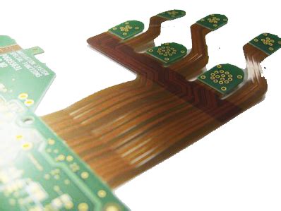
Flexible-Rigid PCBs consist of one or more rigid PCB sections connected by flexible PCB layers. The rigid sections provide structural support and house most of the components, while the flexible sections allow for bending, folding, or twisting of the circuit to fit within confined spaces or to connect multiple rigid sections at various angles.
Key Features of Flexible-Rigid PCBs
- Combination of rigid and flexible substrates
- Increased design flexibility
- Improved reliability
- Reduced assembly costs
- Ability to fit within confined spaces
- Interconnection of multiple rigid sections at various angles
Advantages of Using Flexible-Rigid PCBs
Space Savings and Miniaturization
One of the primary advantages of using Flexible-Rigid PCBs is the ability to save space and achieve miniaturization in electronic devices. By utilizing the flexible sections to fold or bend the circuit, designers can create more compact and efficient layouts compared to using multiple rigid PCBs connected by cables or connectors.
Reduced Assembly Costs
Flexible-Rigid PCBs can help reduce assembly costs by eliminating the need for separate connectors, cables, and wiring between rigid PCB sections. This simplifies the assembly process, reduces the number of components required, and minimizes the risk of assembly errors.
Improved Reliability
The use of Flexible-Rigid PCBs can improve the overall reliability of electronic devices by reducing the number of interconnections and potential failure points. The flexible sections provide a continuous, seamless connection between rigid sections, which can withstand repeated bending and flexing without compromising the electrical integrity of the circuit.
Enhanced Signal Integrity
Flexible-Rigid PCBs offer better signal integrity compared to traditional interconnection methods, such as cables or connectors. The continuous, uninterrupted traces within the flexible sections minimize signal reflections, crosstalk, and electromagnetic interference (EMI), resulting in cleaner and more stable signals.

Designing Flexible-Rigid PCBs
Material Selection
Choosing the right materials is crucial for the success of a Flexible-Rigid PCB design. The rigid sections typically use standard PCB materials, such as FR-4, while the flexible sections use specialized materials like polyimide or polyester. The selection of materials depends on factors such as the required flexibility, temperature range, and dielectric properties.
Layer Stack-up
Designing the layer stack-up for a Flexible-Rigid PCB involves determining the number and arrangement of rigid and flexible layers. The rigid sections can have multiple layers, while the flexible sections usually have fewer layers to maintain flexibility. The stack-up design must consider the required electrical performance, mechanical properties, and manufacturability of the circuit.
Bend Radius and Flexibility
When designing the flexible sections of a Flexible-Rigid PCB, it is essential to consider the bend radius and flexibility requirements. The bend radius refers to the minimum radius at which the flexible section can be bent without causing damage or degrading performance. The flexibility of the circuit depends on factors such as the thickness of the flexible layers, the copper weight, and the properties of the dielectric materials used.
Component Placement and Routing
Component placement and routing on a Flexible-Rigid PCB require careful consideration to ensure proper functionality and reliability. Components should be placed on the rigid sections whenever possible to minimize stress on the components during bending. Routing traces across the flexible sections should be done with caution, avoiding sharp bends or crossing the bend areas at right angles to minimize the risk of trace cracking or breakage.

Manufacturing Flexible-Rigid PCBs
Fabrication Process
The fabrication process for Flexible-Rigid PCBs is more complex than that of standard rigid PCBs due to the combination of rigid and flexible materials. The process typically involves the following steps:
- Fabrication of the rigid and flexible layers separately
- Lamination of the rigid and flexible layers together
- Drilling and plating of through-holes and vias
- Patterning and etching of the copper traces
- Application of solder mask and silkscreen
- Cutting and routing of the panel to the final shape
Lamination and Bonding
Lamination and bonding are critical steps in the manufacturing of Flexible-Rigid PCBs. The rigid and flexible layers must be properly aligned and bonded together to ensure good electrical and mechanical properties. The choice of bonding adhesives and the lamination process parameters, such as temperature, pressure, and time, must be carefully controlled to achieve a reliable and consistent bond between the layers.
Quality Control and Testing
Ensuring the quality and reliability of Flexible-Rigid PCBs requires thorough quality control and testing throughout the manufacturing process. This includes:
- Visual inspection for defects and workmanship issues
- Electrical testing to verify continuity, insulation resistance, and signal integrity
- Mechanical testing to assess the flexibility, bend radius, and durability of the flexible sections
- Environmental testing to ensure the circuit can withstand the intended operating conditions, such as temperature, humidity, and vibration

Assembling Flexible-Rigid PCBs
Surface Mount Technology (SMT)
Surface Mount Technology (SMT) is the preferred method for assembling components on Flexible-Rigid PCBs. SMT allows for smaller components, higher component density, and better performance compared to through-hole technology. When assembling SMT components on flexible sections, it is essential to use low-stress mounting techniques and to provide adequate strain relief to minimize stress on the components during bending.
Soldering Techniques
Soldering components on Flexible-Rigid PCBs requires special considerations to ensure reliable and robust connections. The soldering process must account for the differences in thermal expansion between the rigid and flexible materials, as well as the potential for stress-induced defects. Techniques such as low-temperature soldering, selective soldering, and the use of flexible solder masks can help mitigate these challenges.
Strain Relief and Mechanical Support
Providing proper strain relief and mechanical support is crucial for the long-term reliability of Flexible-Rigid PCBs. Strain relief techniques, such as the use of stiffeners, adhesives, or encapsulants, can help distribute stress and prevent damage to the components and traces in the flexible sections. Mechanical support, such as the use of brackets, clamps, or housing features, can help maintain the desired shape and position of the circuit during use.
Applications of Flexible-Rigid PCBs
Flexible-Rigid PCBs find applications in a wide range of industries and products, including:
- Consumer electronics (smartphones, wearables, laptops)
- Medical devices (implantables, diagnostic equipment)
- Automotive electronics (infotainment systems, sensors)
- Aerospace and defense (avionics, military communications)
- Industrial automation (robotics, machine controls)
The ability of Flexible-Rigid PCBs to combine the benefits of rigid and flexible substrates makes them an attractive choice for applications that require high density, reliability, and design flexibility.
Frequently Asked Questions (FAQ)
1. What is the difference between a Flexible-Rigid PCB and a standard rigid PCB?
A Flexible-Rigid PCB combines both rigid and flexible substrates, allowing for greater design flexibility and the ability to fit within confined spaces. In contrast, a standard rigid PCB uses only rigid substrates and does not have the ability to bend or flex.
2. Can Flexible-Rigid PCBs be used in high-reliability applications?
Yes, Flexible-Rigid PCBs can be used in high-reliability applications, such as medical devices, aerospace, and defense systems. The use of Flexible-Rigid PCBs can improve reliability by reducing the number of interconnections and potential failure points compared to using separate rigid PCBs connected by cables or connectors.
3. What are the challenges in manufacturing Flexible-Rigid PCBs?
Manufacturing Flexible-Rigid PCBs is more complex than standard rigid PCBs due to the combination of rigid and flexible materials. Challenges include ensuring proper alignment and bonding of the layers, controlling the lamination process parameters, and maintaining the desired mechanical and electrical properties of the flexible sections.
4. How do you ensure the reliability of assembled components on Flexible-Rigid PCBs?
To ensure the reliability of assembled components on Flexible-Rigid PCBs, it is important to use low-stress mounting techniques, provide adequate strain relief, and use appropriate soldering methods that account for the differences in thermal expansion between the rigid and flexible materials. Proper mechanical support and the use of stiffeners, adhesives, or encapsulants can also help distribute stress and prevent damage to the components and traces.
5. What are the key considerations when designing a Flexible-Rigid PCB?
When designing a Flexible-Rigid PCB, key considerations include material selection, layer stack-up, bend radius and flexibility requirements, and component placement and routing. Designers must also consider the manufacturability, assembly, and reliability aspects of the circuit to ensure a successful end product.
Conclusion
Flexible-Rigid PCBs offer a unique combination of benefits, allowing for greater design flexibility, improved reliability, and reduced assembly costs compared to traditional rigid PCBs or purely flexible circuits. By understanding the design, manufacturing, and assembly considerations for Flexible-Rigid PCBs, engineers and designers can create more compact, efficient, and reliable electronic devices across a wide range of industries and applications.
As technology continues to advance and the demand for miniaturization and high-performance electronics grows, the use of Flexible-Rigid PCBs is expected to increase. By staying up-to-date with the latest developments in materials, design tools, and manufacturing processes, engineers can leverage the full potential of Flexible-Rigid PCBs to create innovative and reliable products that meet the evolving needs of the market.