Judy@4pcba.com
7:30 AM - 7:30 PM
Monday to Saturday

Archive: June 27, 2023

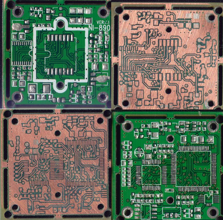
Face Recognition Attendance Machine PCB Copy Board

Face Recognition Attendance Machine PCB Copy Board

Shenzhen Rayming Technology Co., Ltd. is a professional PCB copy, circuit board copy (cloning), chip decryption, PCB design, PCB production processing, copy number, component imitation cloning, software and hardware development and design of technical service enterprises.
Product specifications:


  Facial recognition capacity :400 faces
  Card capacity : 10000 cards
  Record capacity: 100000
  Hardware platform: ZEM800 multimedia development platform
  Camera: high-resolution infrared and color dual camera
  Display: 4.3-inch touch screen
  Communication mode: TCP/IP, RS232/485, USB-HOST
  Attendance function: external timer ringing daylight saving time record query work code
  Access control function: standard with simple access control function (door magnet, door switch, lock control, Wiegand output)
  Power supply: 12V/3A
 Size: 193.6165.286
The product uses the latest ZEM800 core board, fingerprint facial hybrid recognition algorithm, large capacity, fast recognition, high integration, night vision infrared and color camera function, wide range of application, independent of external light, whether in bright light or darkness can also be effectively identified. Can effectively solve the limitations of individual biometric applications, through the beard, glasses, bangs and other coverings, natural expressions, exaggerated expressions can be compared

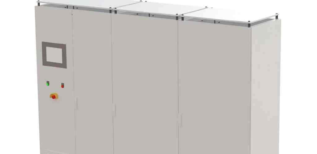
Secondary development case of medium frequency inverter generator

Secondary development case of medium frequency inverter generator

Shenzhen Rayming Technology Co., Ltd. has been providing technical services such as circuit board copy, chip decryption, bill of materials BOM production, circuit board cloning, circuit board prototyping, circuit board soldering, full set of prototype cloning, prototype production and debugging, and full set of product technical data extraction. At the same time, we will enhance the function upgrade and expansion of this product according to the change of market demand and product renewal, and provide customized services for our customers, we look forward to sincere cooperation with our customers.

Main technical parameters:
  1. the rated power of the industrial frequency motor is not specified, but to ensure that the medium frequency generator can output the rated power;
  2. Medium frequency generator: 30KW, 50KW, 75KW, 100KW, 125KW, 200KW;
  3. industrial frequency motor: 50Hz;
  4. Medium frequency generator: 100-200Hz;
  5. Industrial frequency motor: 380V;
  6. Medium frequency generator: 0-800V;
  Number of phases:
  1. industrial frequency motor: 3 groups;
  2. Medium frequency generator: 3 phases;
  Motor connection:
  Industrial frequency motor: △;
  Medium frequency generator: star connection with neutral lead wire;
  Starting of industrial frequency motor: Y-△ starting;

Autopilot PCB copy case of aviation equipment

Autopilot PCB copy case of aviation equipment

Shenzhen Rayming Technology Reverse Research Center has been providing one-stop service for avionics reverse engineering with PCB copy board, chip decryption and software and hardware development. The autopilot PCB copy board secondary development successfully integrates the accumulated decades of experience and wisdom of Shenzhen Rayming professional aviation engineers and copy board team, and immediately achieves the ideal flight effect and control accuracy. In addition, Shenzhen Rayming Technology has listened to the opinions of nearly 10 professional user units and analyzed the typical functional requirements of Chinese users, and can provide the localization research of foreign autopilots and provide software and hardware secondary development and customization services for users to quickly realize their own mission functions.

With the U.S. UAV rampage in China UFO incident, autopilots and other avionics have become important weaponry and can perform intelligence, surveillance and reconnaissance (ISR) missions. Although the development of Chinese UAVs started late, it has developed rapidly in recent years, especially under the promotion of a group of reverse engineering enterprises with the concept of strong nation and the spirit of learning and innovation, the autopilot with independent intellectual property rights developed by Chinese PCB copyboard secondary has been successfully applied to certain naval UAVs and small and medium-sized UAVs, etc.

Technical specifications:
  ●Weight: The circuit board weighs 57g (including flight control, navigation and hand autopilot switching modules), plus 157g after shielding shell, aviation plug, rudder terminal board and GPS antenna
  ●Size: 35×35×120 mm (including shielded case)
  Power consumption: 1200 milliwatts
  ●Using voltage:
  Main power supply: 6.5~10 volts
  Manual switching module: 4.5~10 volts (usually share the battery with the remote receiver)

Operating temperature: -15 to 65 degrees Celsius
  ●Using overload:5G
  ●Destruction overload:200G
  ●Measurement speed range: Airspeed tube 80m/sec, GPS 350m/sec
  Maximum altitude: 4500m The autopilot is successfully developed by the best embedded system developers in our lab with modular PCB reboarding, 120,000 lines of program code, 88 pages of flight control and mission function protocols, which can be considered as one of the most cost-effective miniature autopilots, and compared with similar products, many optional parts have become standard configuration, and there is no limitation and reservation in algorithm and control accuracy without restrictions and reservations. When a device is limited, it can be quickly replaced with a “variant”, so there is no limit to capacity.

Product Overview
  The autopilot has integrated 3-axis MEMS gyroscope, 3-axis MEMS accelerometer, miniature barometric altimeter, miniature airspeed sensor, miniature fluxgate, miniature GPS receiver, etc., which is fully functional and has the same performance as similar products abroad. And Dragonman can measure the aircraft’s three-axis heading in real time through Jetlink solution, so that it can realize the precise attitude control similar to that of large and medium-sized UAVs, which is a function that most similar products do not have. Another feature of this autopilot is that it can realize the re-customization of system software and hardware to make it more suitable for a specific flight platform or task, which is incomparable to similar foreign products.

Hardware configuration features:
  ●The autopilot can include navigation (NAV), flight control (FCS), rudder expansion board (ExServ), user mode expansion board (Ex10), etc. The communication between the 4 is done through CAN bus.
  ● 3 CPU design, flight control computer 66MHz, navigation computer 66MHz, hand drive/self drive switching module 8MHz, hand drive/self drive switching module high reliability design, digital switch direct switching, reduce the risk of test flight. 4M erasable memory, provide up to 2 hours black box data recording function.
  ● Complete sensor configuration, integrated 3-axis MEMS gyro, 3-axis MEMS accelerometer, barometric altimeter, barometric airspeed meter, digital magnetic compass, 12-channel fast star search GPS, which can give more accurate 3D attitude, realize attitude control, give Jetlink heading, and give ground speed and airspeed at the same time.
  ● Powerful expansion capability with 4 channels of rudder servo, 1 channel of throttle servo, 5 channels of mission servo Note 1, 10-bit resolution of servo output, 25Hz update frequency Note 2. Various advanced functions can be expanded via CAN bus, including A/D sampling, up to 128 channels of switching and servo servo, multiple groups of power battery management, online self-test of other avionics systems, etc.

PCB copy board grinding method

PCB copy board grinding method

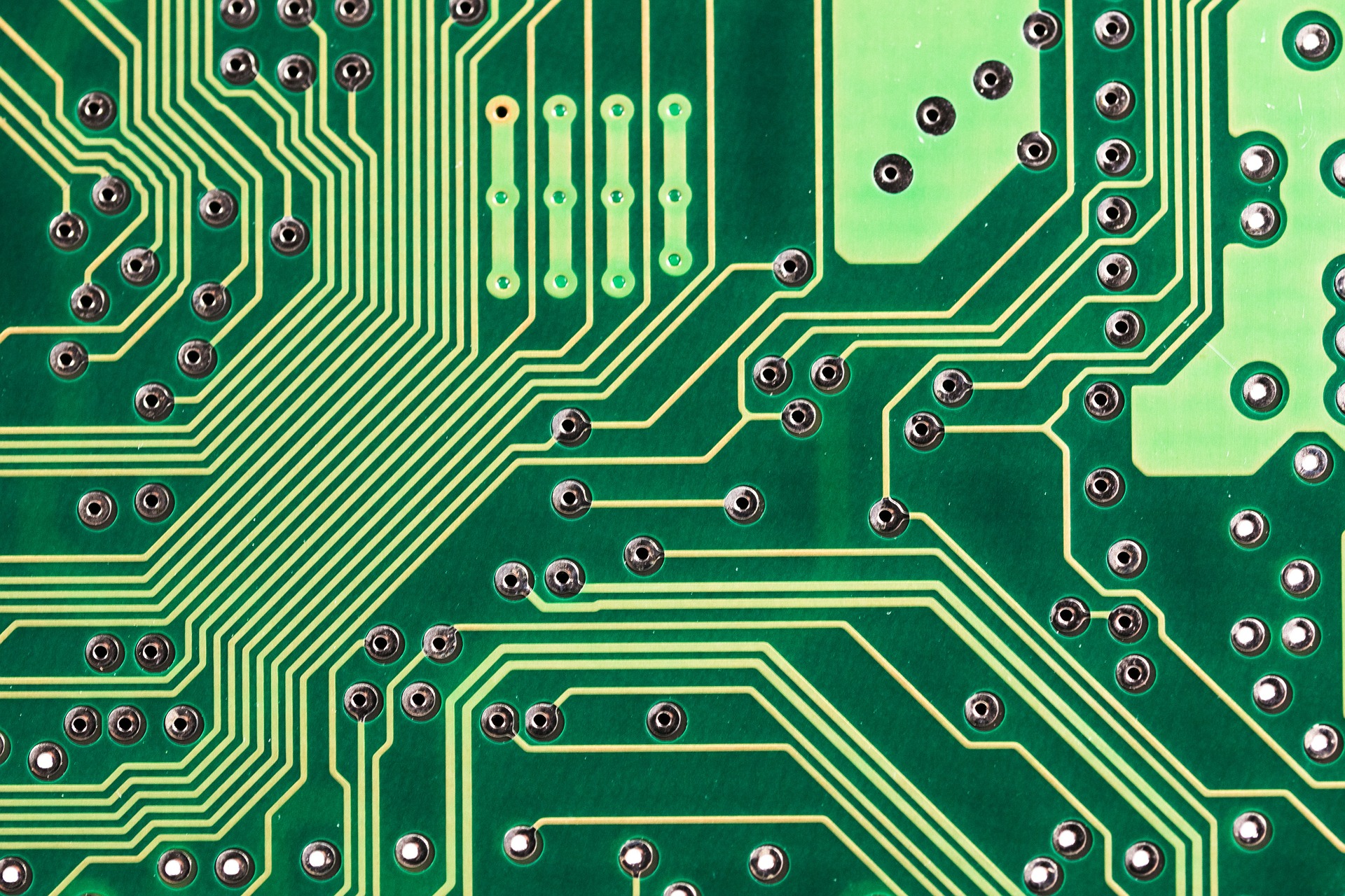
For multilayer boards, the middle layer can not be directly scanned out, to copy the multilayer board must be multi-layer grinding out, so copy multilayer board must be scrapped a PCB board.

The best way to use the current method is to use a good grinder and manual grinding with yarn paper, the latter method is the lowest cost of a method, sandpaper is available anywhere on the market to buy ordinary sandpaper, remember to coarse sandpaper, fine sandpaper is difficult to grind.

The method is very simple, the PCB board according to the level of force with sandpaper grinding, if there is a large piece of copper skin available pliers can be pulled off directly, or with a few flat frustration on the difficult to grind off, and then switch to sandpaper and then grinding.

Grinding board in fact, there is no technical content, purely empirical things, grinding a multi-layer circuit board will understand.

PCB copy board

Explain the process of RAYMING Technology PCB copy board

Explain the PCB copy process:

The first step, get a PCB, first record on paper the model, parameters, and location of all the components, especially the diode, the direction of the three machine tube, the direction of the IC gap.

Step 2, remove all devices and remove the tin from the PAD holes. Clean the PCB with alcohol, then put it into the scanner, start POHTOSHOP, sweep the silkscreen surface in color, and print it out for backup.

Step 3, lightly sand the TOP LAYER and BOTTOM LAYER layers with water yarn paper until the copper film is shiny, put it into the scanner, start PHOTOSHOP, and sweep in the two layers separately in color.

Step 4: Adjust the contrast, lightness and darkness of the canvas, so that the part with copper film and the part without copper film are in strong contrast, then turn the secondary image to black and white, check whether the lines are clear, if not, repeat this step. If clear, save the figure as black and white BMP format files TOP.BMP and BOT.

Fifth, convert the two BMP format files to PROTEL format files respectively, and transfer into two layers in PROTEL, if the position of PAD and VIA over the two layers basically overlap, it shows that the first few steps are well done, if there is deviation, repeat the third step.

Sixth, convert TOP. BMP to TOP. PCB and place the devices according to the drawing in the second step.

Seventh, convert BOT. BMP to BOT. PCB.

Step 8, transfer TOP. PCB and BOT. PCB in PROTEL and combine them into one drawing.

Step 9, use laser printer to print TOP LAYER, BOTTOM LAYER on transparent film (1:1 ratio), put the film on that PCB, and compare whether there is a mistake.

“If you have any demand for copy/change board, we will give you the most reasonable quotation immediately according to your specific requirements, and welcome you to call and visit us for project cooperation negotiation.

Warm tips:
1, where the company for circuit board cloning business customers, must have a legal PCB design copyright source statement, in order to protect the legitimate rights and interests of the original PCB design copyright owners;
2, recently there are more companies on the market with “PCB copy services”, in order to avoid unnecessary losses; to ensure your interests; please confirm the existence of the company or has been revoked;

IC Decode

How the encrypted chip is decrypted

How is the chip decrypted? What steps are needed and why are some chips so costly to decrypt?

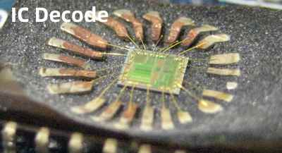
As we all know, in the chip decryption industry, the most correct decryption method is to take the method of hardware decryption, that is, to dissolve the chip with a specific solution, so that the chip is exposed, in the operation of this step, it is also necessary to have some skills. Of course, when operating this step, sometimes, the chip may be dissolved badly, that is, the line is dissolved and broken, so the chip will not be used at all. Of course, if the customer has only one master chip, then you can take it to the binding factory to re-bind, but then, it will incur certain costs, time is also greatly lengthened, generally binding once a week, if the binding test does not pass, then you have to take it again to bind, if such a situation, the technical staff will open a new chip, in order to strive for the shortest possible If such a case, the technician will open another chip again and try to extract the program in the shortest possible time. When the chip is exposed, then we have to use high magnification microscope and FIB (Focused Ion Beam device), with these two devices, find the encrypted position of the chip, change the encrypted chip to a state without encryption by changing its wiring, and then use the programmer to read out the internal program of the chip.

  Chip processing process

  1. Chip open cover Open the cover by chemical method or special package type to open the cover and process the gold line to take out the die.
  2. Layer removal Remove layers by etching, including removing the protective layer polyimide, oxide layer, passivation layer, metal layer, etc.
  3. Chip staining By staining for easy identification, mainly metal layer brightening, different types of trap area staining, ROM code point staining.
  4. Chip photography The chip is photographed by SEM.
  5. Image stitching Stitching the photographed area images (software stitching, manual stitching after photo development).
6.Circuit analysis Capable of extracting digital and analog circuits from chips and organizing them into easy-to-understand hierarchical circuit diagrams, which are released to customers in the form of written reports and electronic data.

High voltage power supply

High voltage power supply board PCB secondary development

PCB Clone of High voltage power supply board

Input voltage: AC220V/380V±10%.

Output voltage: 0V~10KV

Output voltage: 0A~1A

Voltage regulation rate: Relative to load: 0.01% (no-load to rated load) Relative input: ±0.01% (input voltage change of ±10%)

Current regulation rate: Relative to load: 0.01% (no load to rated load) Relative to input: ±0.01% (input voltage change of ±10%)

Ripple voltage: 0.1% of maximum output voltage peak-to-peak at rated output voltage

Ambient temperature: 0 to +50°C at operation. -20°C to +80°C during storage.

Temperature coefficient: 0.01% per degree Celsius.

Remote control of output voltage and current: External potentiometers can be used to remotely control the output voltage and current using the power supply’s internal 10V reference voltage.

Remote voltage and current indication: 25-pin terminal block contains voltage and current indication signals from 0 to 10V, which can be externally connected to various digital or pointer meters.

Handheld radar tachograph

Handheld radar tachograph circuit board copy

Handheld radar tachograph PCB copy

Radar velocimetry is a device that uses radio echoes in order to detect the direction and distance of a target. When the target approaches the radar antenna, the reflected signal frequency will be higher than the transmitter frequency; conversely, when the target goes away from the antenna, the reflected signal frequency will be lower than the transmitter rate. In this way, the relative speed of the target and the radar can be calculated by the change of frequency value.

Technical parameters

Speed range: 5-250: miles / hour 8-400 km / hour

Accuracy: +/- 0.1 mph

Target speed acquisition time: 0.046 seconds (ball) 0.08 seconds (car)

Refresh rate: 25 times/sec

Measurement distance:

4000 feet – passenger car

1500 feet – motorcycle sled

1000 feet – boats

200ft–baseball

Operating frequency: 24.150GHz

Power output: 15 milliwatts

CPU model: 56002DSP

Operating temperature: -28℃–48℃

Storage temperature: -40℃–60℃

With battery handle: 7.5V DC 1.5A current

With cable handle: 9-16V DC

Dimension: 23.5cm (H) × 9cm (W) × 26cm (L)

Shell material: high-strength polycarbonate plastic

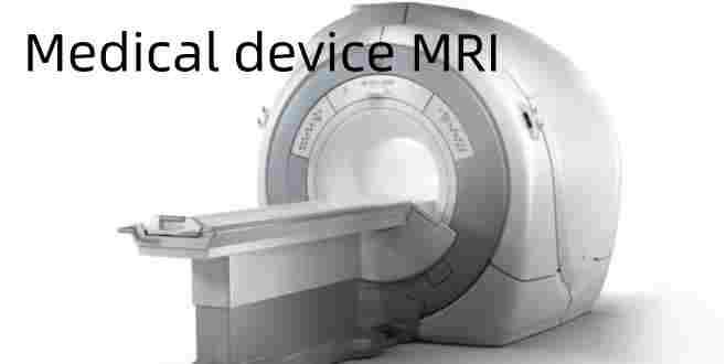
Medical device MRI

Medical device MRI copy board

Magnetic resonance PCB secondary development for medical devices

Medical device MRI Control PCB Copy

Imaging Principle

A medical magnetic resonance imaging system (MRI) consists of a magnet, a coil, a control unit, a computer imaging system and a diagnostic bed. MRI is a biomagnetic nuclear spin imaging technology that has been rapidly developed with the development of computer technology, electronic circuit technology, and superconductor technology. It uses magnetic field and radio frequency pulses to make the hydrogen nucleus (H+) in human tissue in spin motion vibrate to produce radio frequency signals, which are imaged by computer processing. That is, there is a stable magnetic field and an alternating electromagnetic field acting on the sample. After removing the electromagnetic field, the nucleus in the excited state can jump to a lower energy level and radiate electromagnetic waves, and at the same time, a voltage signal can be induced in the coil, which becomes the nuclear magnetic resonance signal. Human tissues contain a large number of hydrogen nuclei due to the presence of large amounts of water and hydrocarbons, and the signals obtained with hydrogen nuclei are generally more than 1000 times larger than other nuclei. The water in human body organs and tissues is not the same, and the pathological process of many diseases will lead to the change of water morphology, which makes the voltage signal of normal tissues different from that of diseased tissues. Combined with the electronic computed tomography (CT) technology, we can get the image of any section of human tissues, especially for the diagnosis of soft tissue lesions, which shows its advantages, the lesion area is very sensitive and the image is clear. If the number of frequency variables of MRI is increased to two or more, two-dimensional or multi-dimensional MRI can be achieved, thus obtaining more information than one-dimensional MRI.

Magnetic field intensity meter: The resolving power is 0.1mT, and the maximum allowable error is not more than one-third of the object to be examined.

The test was performed according to the method recommended by AAPM and the method in the module manual. The performance parameters tested were signal-to-noise ratio, uniformity, linearity error (aberration), layer thickness error, spatial resolving power and low contrast resolving power. Firstly, the performance parameters were grouped according to the field strength, and the relationship between the performance parameters and the field strength was studied. Then, the uniformity, linearity error (aberration), layer thickness error, spatial resolution and low contrast resolution were grouped according to their sizes, and the distribution characteristics of the performance parameters were studied.

3.2.1 Signal-to-noise ratio

All the equipment is divided into 4 groups according to the field strength, the first group field strength <0.5T, for low field strength; the second group field strength of 0.5T ~ 0.9T; the third group field strength of 1.0T ~ 1.5T; the fourth group field strength ≥ 1.5T. Table 2 shows the maximum value, minimum value, extreme difference and average value of signal-to-noise ratio under 4 groups field strength. The average value of S/N ratio varies greatly from group to group, and increases obviously with the increase of field strength.

3.2.2 Uniformity

Uniformity is grouped by field strength, and there is no significant difference in uniformity among groups, see Table 3.

Equipment if grouped by uniformity, the number and percentage of units in each group is shown in Table 4. 97.5% or more of the equipment uniformity in more than 94%, 100% of the equipment uniformity in more than 90%.

3.2.3 Linearity error (aberration)

X-direction linearity error (aberration) grouped by field strength, the average value of X-direction linearity error of each group does not differ significantly, see Table 5.

Equipment if the X-direction linearity error (aberration) grouping, the number and percentage of each group as shown in Table 6. 97.5% or more of the equipment X-direction linearity error (aberration) in less than 5%, 2.5% of the equipment X-direction linearity error (aberration) more than 5%.

Y-direction linearity error (aberration) by field strength grouping, the average value of the Y-direction linearity error of each group is not significantly different, see Table 7. if the linearity error by Y-direction grouping, the number of units in each group and the percentage of Table 8. 97.5% or more of the equipment Y-direction linearity error (aberration) in 1.5% or less, 100% of the equipment Y-direction linearity error (aberration) in 3.5% or less.

3.2.4 Layer thickness error

The layer thickness of 8 devices could not be measured because the signal of some devices’ slant line image was too weak and some devices had no Profile function. For the 32 devices that have measured the layer thickness grouped by field strength, there is no significant difference in the layer thickness error of each group, see Table 9.

If grouped by the size of the layer thickness error, the number of units in each group and the percentage of Table 10. 90% of the equipment layer thickness error is less than 1.0mm, 10% of the equipment layer thickness error is more than 1mm.

3.2.5 Spatial resolution

Because the highest spatial resolution of the device is equal to the size of the pixel, in the measurement of spatial resolution FOV is taken as 256mm, pixel matrix is taken as 256×256, pixel is equal to 1mm, so the highest spatial resolution of the device is equal to 1mm. according to the results of field strength grouping, there is no significant difference in the spatial resolution of each group, see Table 11.

Among the 40 devices, 80% of the devices with spatial resolution of 1mm and 20% of the devices with spatial resolution of 1.25mm.

3.2.6 Low-contrast resolving power

According to the field strength grouping, the low contrast resolution is related to the field strength, as shown in Table 12. the devices with the field strength equal to and higher than 0.5T can distinguish the hole of Φ4mm/0.5mm deep, among the devices with the field strength lower than 0.5T, the devices with the low contrast resolution of Φ4mm/0.5mm deep account for 83%, and the devices with Φ6mm/0.5mm deep account for 17%

4 Discussion

The criteria for MRI clinical application performance proposed in the AAPM 100 report are quality assurance standards that are applicable to all manufacturers and models of equipment. Based on the statistical analysis of the test results of 40 MRI devices of different manufacturers and different field strengths, the following evaluations of the relevant standards were made:

4.1 Signal-to-noise ratio with respect to field strength

The field strengths of the 40 MRI devices were divided into the following four groups: <0.5 T, 0.5 T to 0.9 T, 1.0 T to 1.5, and ≥1.5 T. The average signal-to-noise ratio of each group increased with field strength, and was 77, 112, 194, and 270, respectively. The AAPM report did not propose a standard for signal-to-noise ratio, and different standards must be adopted for different field strengths if a standard for signal-to-noise ratio is to be specified.

4.2 Uniformity is independent of field strength

Among the 40 MRI devices, 100% of the devices had a uniformity of 90% or more. the uniformity standard recommended by the AAPM report is 80%, which is too low from the results of the experimental tests. With the advancement of MRI technology and the improvement of equipment performance, this performance has generally improved.

4.3 Linearity errors (aberrations) are independent of field strength

The linearity error recommended by the AAPM report is 5%, and the results of the test show that this standard is appropriate.

4.4 Layer thickness error is independent of field strength

Among the 32 devices with measured layer thickness, 90% of the devices have layer thickness error less than 1.0mm, and 10% of the devices have layer thickness error more than 1.0mm. The standard of layer thickness error introduced by the AAPM report is ±1mm, and the standard is also appropriate from the test results.

4.5 Spatial resolution is independent of field strength

The spatial resolution standard introduced by the AAPM report is 1mm, which is the ideal spatial resolution, from the test results only 79.4% of the equipment can reach this standard, there are still 20.6% of the equipment can not reach. The standard as a quality assurance standard is okay, but as the standard of clinical application quality is too high, according to the standard, there will be part of the equipment clinical application quality failed.

4.6 Low-contrast resolving power related to field strength

This parameter is not included in the performance parameters of MRI equipment proposed in the AAPM report, but we believe that this parameter is indispensable. Because the low contrast resolution is different from the spatial resolution, the latter is the ability to distinguish the target under high contrast conditions, and the former is the ability to distinguish the target under low contrast conditions, both are performance parameters directly related to the quality of clinical diagnosis. The low-contrast resolution can be quantitatively detected by specially designed body model. From the results of experimental testing, the low-contrast resolution is related to the field strength, and the devices with the field strength equal to or higher than 0.5T can distinguish the holes of Φ4mm/0.5mm deep, and 83% of the devices with the field strength lower than 0.5T can distinguish the holes of Φ4mm/0.5mm deep, and 17% of the devices can distinguish the holes of Φ6mm/0.5mm deep. 0.5mm deep hole. Therefore, the low contrast resolution standard should be set according to the different field strength.

Our PCB copy board team has accumulated 17 years of technical experience in Shenzhen and has been involved in almost all electronic products PCB circuit boards, especially for various high-precision special circuit boards and various multi-layer PCB copy board experience for many years, and has a better understanding of the structure and alignment rules of complex PCB boards containing laser holes, blind holes and buried holes. Under the premise of the reverse R & D technology means to reverse analysis of the circuit board, the original product PCB files, bill of materials (BOM) files, schematic files and other technical documents and PCB screen printing production files for 1:1 restoration, and then use these technical documents and production files for PCB board, component welding, flying probe test, circuit board debugging, complete the original circuit board prototype board complete copy of the original circuit board prototype.

With the advanced scanning technology, the latest copy software and the most experienced senior technical team in China, we have been providing various single-layer, double-layer, multi-layer PCB board copy, various blind buried hole boards, laser blind hole boards, UHF boards, ceramic PCB copy boards, component density, long lines all over the microstrip lines, high frequency processing requirements and strict EMC control of the communication board copy services, customers only need to provide a complete set of sample boards or a complete set of sample boards. Customers only need to provide a complete set of prototypes or prototypes, Qingbao Technology promises to copy the board at once, change the board, debugging, copy the accuracy of the board to 1mil.
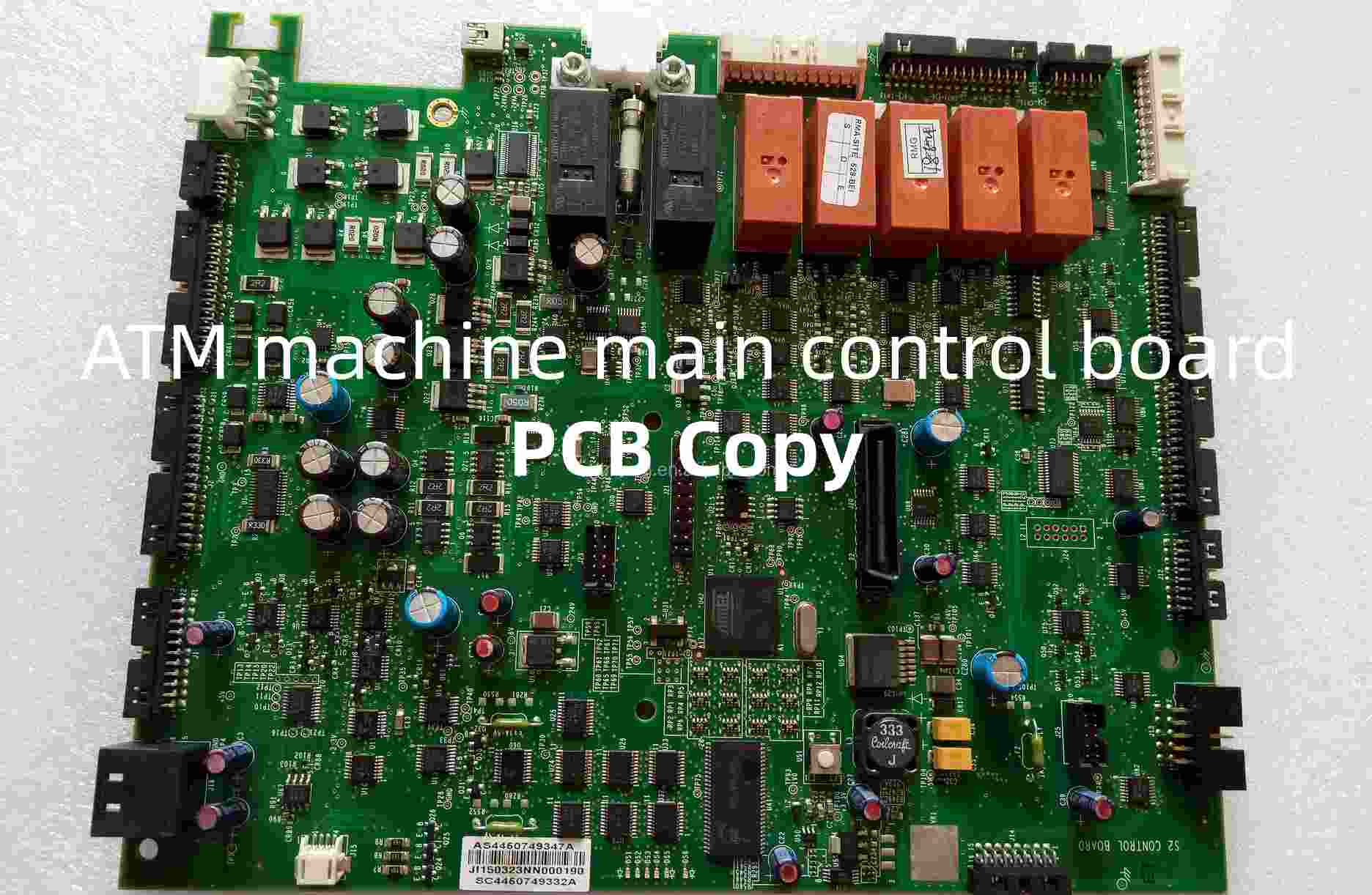
ATM machine main control board