Judy@4pcba.com
7:30 AM - 7:30 PM
Monday to Saturday

PCB COPY

9 Tips for Choosing the Right Rigid-flex PCB Manufacturer

Introduction to Rigid-flex PCBs

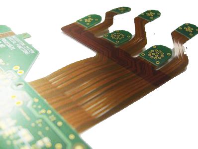
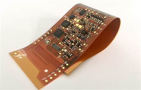
Rigid-flex PCBs are a unique type of printed circuit board that combines the benefits of both rigid and flexible PCBs. They consist of rigid PCB sections connected by flexible PCB sections, allowing for three-dimensional packaging and improved reliability in applications that require flexibility or space savings.

Rigid-flex PCBs offer several advantages over traditional PCBs:

  1. Reduced weight and size
  2. Improved reliability and durability
  3. Enhanced electrical performance
  4. Increased design flexibility
  5. Simplified assembly process

As the demand for smaller, more complex electronic devices grows, rigid-flex PCBs are becoming increasingly popular in various industries, including:

  • Aerospace and defense
  • Medical devices
  • Automotive electronics
  • Consumer electronics
  • Industrial automation

The Importance of Choosing the Right Rigid-flex PCB Manufacturer

Selecting the right rigid-flex PCB manufacturer is crucial to ensuring the success of your project. A reliable manufacturer will have the expertise, equipment, and quality control processes in place to produce high-quality rigid-flex PCBs that meet your specific requirements.

Choosing the wrong manufacturer can lead to several issues, such as:

  1. Inferior product quality
  2. Delays in production and delivery
  3. Increased costs due to rework or replacements
  4. Compliance issues with industry standards and regulations
  5. Damage to your company’s reputation

To avoid these problems and ensure the success of your project, it’s essential to carefully evaluate potential rigid-flex PCB manufacturers and select the one that best meets your needs.

Tip 1: Evaluate the Manufacturer’s Experience and Expertise

When choosing a rigid-flex PCB manufacturer, it’s important to consider their experience and expertise in producing rigid-flex PCBs. Look for a manufacturer with a proven track record of successfully delivering high-quality rigid-flex PCBs for projects similar to yours.

Some factors to consider when evaluating a manufacturer’s experience and expertise include:

  1. Years in the industry
  2. Types of rigid-flex PCBs produced
  3. Industries served
  4. Certifications and qualifications
  5. Customer testimonials and case studies

An experienced manufacturer will have the knowledge and skills necessary to navigate the unique challenges of rigid-flex PCB design and manufacturing, ensuring that your project is completed efficiently and to your specifications.

Tip 2: Assess the Manufacturer’s Quality Control Processes

Quality control is essential in rigid-flex PCB manufacturing to ensure that the final product meets your requirements and functions as intended. When evaluating potential manufacturers, inquire about their quality control processes and procedures.

A reputable rigid-flex PCB manufacturer should have:

  1. Documented quality management system (QMS)
  2. Adherence to industry standards (e.g., IPC, ISO, AS9100)
  3. Incoming material inspection and verification
  4. In-process quality checks and testing
  5. Final inspection and functional testing
  6. Traceability and record-keeping

By choosing a manufacturer with robust quality control processes, you can minimize the risk of receiving defective or substandard rigid-flex PCBs that could jeopardize your project’s success.

Tip 3: Consider the Manufacturer’s Capacity and Lead Times

When selecting a rigid-flex PCB manufacturer, it’s crucial to ensure that they have the capacity to meet your production needs and can deliver your order within the required lead times.

Factors to consider when assessing a manufacturer’s capacity and lead times include:

  1. Manufacturing facility size and equipment
  2. Production volume capabilities
  3. Typical lead times for rigid-flex PCBs
  4. Ability to accommodate rush orders or varying demand
  5. Inventory management and supply chain stability

Choosing a manufacturer with sufficient capacity and reliable lead times will help prevent delays in your project timeline and ensure that you receive your rigid-flex PCBs when you need them.

Tip 4: Evaluate the Manufacturer’s Design Support Capabilities

Rigid-flex PCB design can be complex, and having access to expert design support from your manufacturer can be invaluable in ensuring the success of your project. Look for a manufacturer that offers comprehensive design support services, such as:

  1. Design for manufacturability (DFM) analysis
  2. Signal integrity analysis
  3. Thermal analysis
  4. 3D modeling and simulation
  5. Prototyping and testing

A manufacturer with strong design support capabilities can help optimize your rigid-flex PCB design, identify and resolve potential issues early in the process, and ensure that your design is ready for production.

Tip 5: Consider the Manufacturer’s Technical Support and Customer Service

In addition to design support, it’s important to choose a rigid-flex PCB manufacturer that offers reliable technical support and customer service throughout the production process and beyond.

Look for a manufacturer that provides:

  1. Dedicated project management
  2. Regular communication and progress updates
  3. Timely responses to technical inquiries
  4. Post-delivery support and warranty
  5. Flexibility in accommodating changes or special requests

A manufacturer with strong technical support and customer service will be a valuable partner in ensuring the success of your rigid-flex PCB project.

Tip 6: Evaluate the Manufacturer’s Manufacturing Capabilities

Rigid-flex PCB manufacturing requires specialized equipment and processes to produce high-quality boards reliably. When choosing a manufacturer, evaluate their manufacturing capabilities to ensure they can meet your specific requirements.

Key manufacturing capabilities to consider include:

  1. Layer count and board thickness
  2. Material selection and compatibility
  3. Minimum feature sizes (e.g., line width, spacing, hole size)
  4. Surface finishes and soldermasks
  5. Controlled impedance
  6. Flex circuit coverlay materials and adhesives

A manufacturer with advanced manufacturing capabilities will be better equipped to produce complex rigid-flex PCBs that meet your design specifications and performance requirements.

Tip 7: Consider the Manufacturer’s Environmental Compliance and Sustainability

As environmental regulations become more stringent and consumers demand more eco-friendly products, it’s important to choose a rigid-flex PCB manufacturer that prioritizes environmental compliance and sustainability.

Look for a manufacturer that:

  1. Complies with environmental regulations (e.g., RoHS, REACH, WEEE)
  2. Implements sustainable manufacturing practices
  3. Uses eco-friendly materials and processes
  4. Has a documented environmental management system (EMS)
  5. Demonstrates a commitment to reducing waste and energy consumption

By selecting an environmentally responsible rigid-flex PCB manufacturer, you can ensure that your products meet regulatory requirements and appeal to environmentally conscious customers.

Tip 8: Evaluate the Manufacturer’s Pricing and Value

While price is an important consideration when choosing a rigid-flex PCB manufacturer, it’s essential to evaluate the overall value they provide rather than focusing solely on the lowest price.

Factors to consider when evaluating pricing and value include:

  1. Cost per unit and volume discounts
  2. Setup and tooling costs
  3. Minimum order quantities (MOQs)
  4. Shipping and logistics costs
  5. Value-added services (e.g., design support, testing, assembly)

A manufacturer that offers competitive pricing along with high-quality products, reliable service, and comprehensive support will provide the best overall value for your rigid-flex PCB project.

Tip 9: Verify the Manufacturer’s References and Reputation

Before making a final decision, it’s essential to verify the references and reputation of the rigid-flex PCB manufacturers you are considering. This will help you gauge their reliability, quality, and customer satisfaction.

Steps to verify a manufacturer’s references and reputation include:

  1. Request and contact customer references
  2. Review online reviews and ratings
  3. Check for any complaints or legal issues
  4. Verify certifications and compliance with industry standards
  5. Visit the manufacturer’s facility, if possible

By thoroughly vetting potential manufacturers, you can make an informed decision and choose a partner that will help ensure the success of your rigid-flex PCB project.

Conclusion

Choosing the right rigid-flex PCB manufacturer is critical to the success of your project. By following these nine tips and carefully evaluating potential manufacturers based on their experience, expertise, quality control, capacity, design support, technical support, manufacturing capabilities, environmental compliance, pricing, and reputation, you can select a reliable partner that will help bring your rigid-flex PCB design to life.

Investing time and effort in the selection process will pay off in the form of high-quality rigid-flex PCBs that meet your requirements, are delivered on time, and perform as intended. With the right manufacturer by your side, you can confidently navigate the complexities of rigid-flex PCB design and manufacturing and bring your innovative products to market successfully.

FAQ

1. What are the benefits of using rigid-flex PCBs?

Rigid-flex PCBs offer several benefits, including reduced weight and size, improved reliability and durability, enhanced electrical performance, increased design flexibility, and simplified assembly processes.

2. How do I determine if a rigid-flex PCB manufacturer has the necessary experience and expertise?

To evaluate a manufacturer’s experience and expertise, consider factors such as their years in the industry, types of rigid-flex PCBs produced, industries served, certifications and qualifications, and customer testimonials or case studies.

3. What should I look for in a manufacturer’s quality control processes?

A reputable rigid-flex PCB manufacturer should have a documented quality management system, adhere to industry standards, conduct incoming material inspections, perform in-process quality checks and testing, carry out final inspections and functional testing, and maintain traceability and record-keeping.

4. How can I ensure that a manufacturer can meet my production needs and lead times?

To assess a manufacturer’s capacity and lead times, consider factors such as their manufacturing facility size and equipment, production volume capabilities, typical lead times for rigid-flex PCBs, ability to accommodate rush orders or varying demand, and inventory management and supply chain stability.

5. What environmental compliance and sustainability factors should I consider when choosing a rigid-flex PCB manufacturer?

Look for a manufacturer that complies with environmental regulations (e.g., RoHS, REACH, WEEE), implements sustainable manufacturing practices, uses eco-friendly materials and processes, has a documented environmental management system, and demonstrates a commitment to reducing waste and energy consumption.

Air Quality Sensor: A Comprehensive Guide

What are Air Quality Sensors?

Air quality sensors are electronic devices that detect and measure the concentration of various pollutants in the air, such as:

  • Particulate matter (PM2.5 and PM10)
  • Volatile organic compounds (VOCs)
  • Carbon monoxide (CO)
  • Nitrogen dioxide (NO2)
  • Sulfur dioxide (SO2)
  • Ozone (O3)

These sensors convert the presence of pollutants into electrical signals, which are then processed and interpreted to provide readable data about air quality.

Types of Air Quality Sensors

There are several types of air quality sensors available, each designed to detect specific pollutants. Some of the most common types include:

1. Optical Sensors

Optical sensors use light scattering techniques to detect and measure particulate matter in the air. They work by illuminating the air sample with a laser or LED and measuring the amount of light scattered by the particles. Examples include:

  • Light scattering sensors
  • Nephelometers
  • Optical particle counters

2. Chemical Sensors

Chemical sensors detect the presence of specific gases in the air by measuring changes in electrical properties or through chemical reactions. Some common chemical sensors are:

  • Electrochemical sensors
  • Metal oxide semiconductor sensors
  • Non-dispersive infrared (NDIR) sensors
  • Photoionization detectors (PID)

3. Biological Sensors

Biological sensors use living organisms or biological materials to detect the presence of pollutants in the air. These sensors are less common but can be used to detect specific biological contaminants, such as:

  • Bacteria
  • Viruses
  • Fungi
  • Allergens

How Air Quality Sensors Work

The working principle of air quality sensors varies depending on the type of sensor and the pollutants it is designed to detect. However, most sensors follow a general process:

  1. Air sample collection: The sensor draws in an air sample from the environment.

  2. Pollutant detection: The sensor uses a specific detection method (e.g., light scattering, chemical reaction, or biological interaction) to identify the presence and concentration of pollutants in the air sample.

  3. Signal conversion: The sensor converts the detected pollutant levels into electrical signals.

  4. Data processing: The electrical signals are processed and converted into readable data, such as pollutant concentrations in parts per million (ppm) or micrograms per cubic meter (µg/m³).

  5. Data output: The processed data is displayed on the sensor’s screen or transmitted to a connected device or network for further analysis and monitoring.

Applications of Air Quality Sensors

Air quality sensors have a wide range of applications, including:

1. Indoor Air Quality Monitoring

Air quality sensors can be used to monitor the air quality in homes, offices, schools, and other indoor environments. They help identify sources of indoor air pollution, such as:

  • Volatile organic compounds (VOCs) from cleaning products, paints, and furniture
  • Carbon monoxide from faulty heating systems or appliances
  • Particulate matter from smoking, cooking, or pet dander

By monitoring indoor air quality, people can take steps to reduce their exposure to harmful pollutants and improve their health and well-being.

2. Outdoor Air Quality Monitoring

Air quality sensors are also used to monitor outdoor air quality in cities, industrial areas, and other locations. They provide real-time data on pollutant levels, which can be used to:

  • Inform public health decisions
  • Develop air quality management strategies
  • Identify sources of air pollution
  • Alert the public during air quality emergencies

Outdoor air quality monitoring networks, such as the U.S. Environmental Protection Agency’s (EPA) AirNow system, rely on data from numerous air quality sensors to provide accurate and up-to-date information on air quality across the country.

3. Industrial Emissions Monitoring

Air quality sensors are used in industrial settings to monitor emissions from manufacturing processes, power plants, and other sources. They help ensure compliance with air quality regulations and can be used to:

  • Detect leaks or malfunctions in emission control systems
  • Optimize industrial processes to reduce emissions
  • Provide data for regulatory reporting

Industrial emissions monitoring is critical for protecting public health and the environment from the harmful effects of air pollution.

4. Personal Exposure Monitoring

Wearable air quality sensors allow individuals to monitor their personal exposure to air pollutants throughout the day. These sensors can be integrated into smartwatches, clothing, or other accessories and provide real-time data on the user’s exposure to pollutants such as particulate matter, VOCs, and carbon monoxide.

Personal exposure monitoring can help individuals identify sources of air pollution in their daily lives and take steps to reduce their exposure, such as avoiding heavily polluted areas or adjusting their activities during high-pollution events.

Benefits of Air Quality Sensors

Air quality sensors offer numerous benefits, including:

  1. Improved public health: By providing real-time data on air quality, sensors can help individuals and communities take steps to reduce their exposure to harmful pollutants and improve their health.

  2. Enhanced environmental protection: Air quality sensors can help identify sources of air pollution and inform strategies to reduce emissions and protect the environment.

  3. Increased awareness: By making air quality data more accessible and understandable, sensors can help raise awareness about the importance of clean air and the impact of air pollution on health and the environment.

  4. Better decision-making: Air quality data from sensors can inform public health decisions, urban planning, and environmental policies, leading to more effective solutions to air pollution problems.

  5. Cost-effective monitoring: Air quality sensors are often more cost-effective than traditional monitoring methods, making it possible to deploy more sensors and obtain more comprehensive data on air quality.

FAQ

1. How accurate are air quality sensors?

The accuracy of air quality sensors varies depending on the type of sensor and the pollutants it is designed to detect. High-quality sensors can provide accurate and reliable data, but some low-cost sensors may have limitations in terms of sensitivity, selectivity, and calibration. It is important to choose sensors from reputable manufacturers and to regularly calibrate and maintain them to ensure accurate readings.

2. Can air quality sensors detect all types of pollutants?

No single air quality sensor can detect all types of pollutants. Different sensors are designed to detect specific pollutants, such as particulate matter, VOCs, or gases like carbon monoxide or nitrogen dioxide. To obtain a comprehensive assessment of air quality, it may be necessary to use multiple sensors or a multi-sensor device that can detect a range of pollutants.

3. How often should air quality sensors be calibrated?

The frequency of calibration depends on the type of sensor and the manufacturer’s recommendations. Some sensors may require calibration every few months, while others may be factory-calibrated and require less frequent adjustments. It is important to follow the manufacturer’s guidelines and to regularly check the sensor’s performance to ensure accurate readings.

4. Can air quality sensors be used outdoors?

Yes, air quality sensors can be used both indoors and outdoors. Outdoor sensors are typically designed to withstand various weather conditions and may have additional features, such as solar panels for power or wireless communication capabilities for remote monitoring.

5. How do I interpret the data from air quality sensors?

Air quality data is typically presented in terms of pollutant concentrations, such as parts per million (ppm) or micrograms per cubic meter (µg/m³). Different pollutants have different health and environmental effects, and there are established air quality standards and guidelines that can help interpret the data. For example, the U.S. EPA has set National Ambient Air Quality Standards (NAAQS) for six common air pollutants, which can be used as a reference for evaluating air quality sensor data. Additionally, many air quality sensors come with mobile apps or web interfaces that provide user-friendly data visualization and interpretation tools.

Conclusion

Air quality sensors are valuable tools for monitoring and improving the air we breathe. By providing real-time data on pollutant levels, these sensors can help individuals, communities, and decision-makers take action to reduce air pollution and protect public health and the environment. As technology continues to advance, air quality sensors are becoming more accurate, affordable, and accessible, making it easier than ever to monitor and improve air quality.

With a better understanding of the types of sensors available, their working principles, and their applications, individuals and organizations can make informed decisions about how to use air quality sensors to create healthier and more sustainable environments. By prioritizing clean air and taking action to reduce pollution, we can all contribute to a better future for ourselves and the planet.

Pollutant Sensor Type Measurement Range Unit
Particulate Matter (PM2.5) Optical 0-1000 µg/m³
Volatile Organic Compounds (VOCs) Metal Oxide Semiconductor 0-1000 ppb
Carbon Monoxide (CO) Electrochemical 0-1000 ppm
Nitrogen Dioxide (NO2) Electrochemical 0-20 ppm
Sulfur Dioxide (SO2) Electrochemical 0-20 ppm
Ozone (O3) Electrochemical 0-10 ppm

Table 1: Common air quality sensor types, measurement ranges, and units.

Air Quality Index (AQI) PM2.5 (µg/m³) Health Concern
0-50 (Good) 0-12 Little or no risk
51-100 (Moderate) 12.1-35.4 Acceptable quality, but some pollutants may pose a moderate health concern for sensitive groups
101-150 (Unhealthy for Sensitive Groups) 35.5-55.4 Members of sensitive groups may experience health effects, but the general public is less likely to be affected
151-200 (Unhealthy) 55.5-150.4 Some members of the general public may experience health effects; sensitive groups may experience more serious health effects
201-300 (Very Unhealthy) 150.5-250.4 Health alert: The risk of health effects is increased for everyone
301+ (Hazardous) 250.5+ Health warning of emergency conditions: Everyone is more likely to be affected

Table 2: U.S. EPA Air Quality Index (AQI) categories, PM2.5 concentration ranges, and associated health concerns.

10 Issues We Need to Pay Attention to in PCB Soldering

1. Insufficient Solder

One of the most common issues in PCB Soldering is insufficient solder. This occurs when not enough solder is applied to the joint, resulting in a weak connection. Insufficient solder can cause intermittent connectivity issues or even complete failure of the electronic device.

Causes of Insufficient Solder

Cause Description
Incorrect solder wire diameter Using a solder wire with a diameter that is too small can result in insufficient solder.
Incorrect soldering iron temperature If the soldering iron temperature is too low, the solder may not melt properly, resulting in insufficient solder.
Incorrect soldering technique If the soldering iron is not applied to the joint for long enough or at the correct angle, insufficient solder may be applied.

Solutions for Insufficient Solder

To prevent insufficient solder, it is important to:

  1. Use the correct solder wire diameter for the job.
  2. Ensure that the soldering iron temperature is set correctly.
  3. Use the correct soldering technique, applying the soldering iron to the joint for the appropriate amount of time and at the correct angle.

2. Excess Solder

On the other hand, applying too much solder can also be a problem. Excess solder can cause short circuits, bridging between adjacent pins, and other issues that can affect the functionality of the electronic device.

Causes of Excess Solder

Cause Description
Incorrect solder wire diameter Using a solder wire with a diameter that is too large can result in excess solder.
Incorrect soldering iron temperature If the soldering iron temperature is too high, the solder may flow too freely, resulting in excess solder.
Incorrect soldering technique If the soldering iron is applied to the joint for too long or at the incorrect angle, excess solder may be applied.

Solutions for Excess Solder

To prevent excess solder, it is important to:

  1. Use the correct solder wire diameter for the job.
  2. Ensure that the soldering iron temperature is set correctly.
  3. Use the correct soldering technique, applying the soldering iron to the joint for the appropriate amount of time and at the correct angle.
  4. Use a solder wick or desoldering pump to remove excess solder if necessary.

3. Cold Solder Joints

Cold solder joints occur when the solder does not melt properly, resulting in a dull, rough, or cracked appearance. Cold solder joints can cause intermittent connectivity issues or complete failure of the electronic device.

Causes of Cold Solder Joints

Cause Description
Incorrect soldering iron temperature If the soldering iron temperature is too low, the solder may not melt properly, resulting in a cold solder joint.
Incorrect soldering technique If the soldering iron is not applied to the joint for long enough or at the correct angle, a cold solder joint may occur.
Dirty or oxidized surfaces If the surfaces to be soldered are dirty or oxidized, the solder may not adhere properly, resulting in a cold solder joint.

Solutions for Cold Solder Joints

To prevent cold solder joints, it is important to:

  1. Ensure that the soldering iron temperature is set correctly.
  2. Use the correct soldering technique, applying the soldering iron to the joint for the appropriate amount of time and at the correct angle.
  3. Clean and prepare the surfaces to be soldered properly.
  4. Reheat the joint and apply additional solder if necessary.

4. Solder Bridges

Solder bridges occur when solder flows between adjacent pins or pads, creating an unintended connection. Solder bridges can cause short circuits and other issues that can affect the functionality of the electronic device.

Causes of Solder Bridges

Cause Description
Excess solder Applying too much solder can cause it to flow between adjacent pins or pads, creating a solder bridge.
Incorrect component placement If components are placed too close together, solder can flow between them, creating a solder bridge.
Incorrect soldering technique If the soldering iron is not applied to the joint carefully, solder can flow between adjacent pins or pads, creating a solder bridge.

Solutions for Solder Bridges

To prevent solder bridges, it is important to:

  1. Use the correct amount of solder for the job.
  2. Ensure that components are placed with sufficient spacing between them.
  3. Use the correct soldering technique, applying the soldering iron to the joint carefully and accurately.
  4. Use a solder wick or desoldering pump to remove solder bridges if necessary.

5. Tombstoning

Tombstoning occurs when a surface-mount component stands up on one end during the soldering process, resulting in a poor or non-existent connection on one side of the component. Tombstoning can cause intermittent connectivity issues or complete failure of the electronic device.

Causes of Tombstoning

Cause Description
Uneven heating If one side of the component is heated more than the other, it can cause the component to stand up on one end.
Incorrect component placement If the component is not placed flat on the PCB, it can stand up on one end during the soldering process.
Incorrect pad design If the pads for the component are not designed correctly, it can cause the component to stand up on one end.

Solutions for Tombstoning

To prevent tombstoning, it is important to:

  1. Ensure that the component is heated evenly on both sides.
  2. Place the component flat on the PCB and ensure that it is aligned correctly.
  3. Design the pads for the component correctly, with sufficient size and spacing.

6. Solder Balls

Solder balls are small spheres of solder that can form on the PCB during the soldering process. Solder balls can cause short circuits and other issues that can affect the functionality of the electronic device.

Causes of Solder Balls

Cause Description
Excess solder Applying too much solder can cause it to form into small spheres on the PCB.
Incorrect soldering technique If the soldering iron is not applied to the joint carefully, solder can splatter and form into small spheres on the PCB.
Contaminated solder If the solder is contaminated with impurities, it can form into small spheres on the PCB.

Solutions for Solder Balls

To prevent solder balls, it is important to:

  1. Use the correct amount of solder for the job.
  2. Use the correct soldering technique, applying the soldering iron to the joint carefully and accurately.
  3. Use high-quality, uncontaminated solder.
  4. Use a solder wick or desoldering pump to remove solder balls if necessary.

7. Lifted Pads

Lifted pads occur when the copper pad on the PCB separates from the board during the soldering process. Lifted pads can cause intermittent connectivity issues or complete failure of the electronic device.

Causes of Lifted Pads

Cause Description
Incorrect soldering iron temperature If the soldering iron temperature is too high, it can cause the copper pad to separate from the PCB.
Incorrect soldering technique If the soldering iron is applied to the joint with too much force or for too long, it can cause the copper pad to separate from the PCB.
Poor PCB quality If the PCB is of poor quality, the copper pads may not be properly bonded to the board, making them more likely to lift during the soldering process.

Solutions for Lifted Pads

To prevent lifted pads, it is important to:

  1. Ensure that the soldering iron temperature is set correctly.
  2. Use the correct soldering technique, applying the soldering iron to the joint with the appropriate amount of force and for the appropriate amount of time.
  3. Use high-quality PCBs with properly bonded copper pads.
  4. Repair lifted pads using conductive epoxy or by soldering a wire jumper to the affected pad.

8. Flux Residue

Flux is a chemical used in the soldering process to help the solder flow and adhere to the surfaces being joined. However, if the flux is not cleaned off the PCB after soldering, it can leave a residue that can cause corrosion and other issues.

Causes of Flux Residue

Cause Description
Incorrect flux type Using the wrong type of flux for the job can result in excess residue.
Insufficient cleaning If the PCB is not cleaned properly after soldering, flux residue can remain on the board.
Incorrect cleaning method Using the wrong cleaning method or solution can leave flux residue on the PCB.

Solutions for Flux Residue

To prevent flux residue, it is important to:

  1. Use the correct type of flux for the job.
  2. Clean the PCB thoroughly after soldering using an appropriate cleaning solution and method.
  3. Inspect the PCB for any remaining flux residue and clean again if necessary.

9. Incorrect Component Orientation

Incorrect component orientation occurs when a component is placed on the PCB in the wrong direction or orientation. This can cause the electronic device to malfunction or not work at all.

Causes of Incorrect Component Orientation

Cause Description
Human error Incorrectly placing a component on the PCB due to inattention or mistaken identification.
Incorrect component markings If the component markings are unclear or incorrect, it can lead to incorrect orientation.
Incorrect PCB design If the PCB is designed with the incorrect component orientation, it can lead to incorrect placement during assembly.

Solutions for Incorrect Component Orientation

To prevent incorrect component orientation, it is important to:

  1. Double-check component orientation before soldering.
  2. Use clear and correct component markings.
  3. Design the PCB with the correct component orientation.
  4. Use a pick-and-place machine for automated assembly to reduce the risk of human error.

10. Overheated Components

Overheating components during the soldering process can cause damage to the component or the PCB, leading to reduced reliability or complete failure of the electronic device.

Causes of Overheated Components

Cause Description
Incorrect soldering iron temperature If the soldering iron temperature is too high, it can cause the component to overheat.
Incorrect soldering technique If the soldering iron is applied to the component for too long, it can cause the component to overheat.
Insufficient heat sinking If the component generates a lot of heat during operation and does not have sufficient heat sinking, it can overheat during the soldering process.

Solutions for Overheated Components

To prevent overheated components, it is important to:

  1. Ensure that the soldering iron temperature is set correctly for the component being soldered.
  2. Use the correct soldering technique, applying the soldering iron to the component for the appropriate amount of time.
  3. Provide sufficient heat sinking for components that generate a lot of heat during operation.
  4. Use a temperature-controlled soldering station to avoid overheating the component.

FAQ

1. What is the most common issue in PCB soldering?

The most common issue in PCB soldering is insufficient solder, which can cause intermittent connectivity issues or complete failure of the electronic device.

2. How can I prevent solder bridges?

To prevent solder bridges, it is important to use the correct amount of solder for the job, ensure that components are placed with sufficient spacing between them, and use the correct soldering technique, applying the soldering iron to the joint carefully and accurately.

3. What causes tombstoning in surface-mount components?

Tombstoning can be caused by uneven heating, incorrect component placement, or incorrect pad design. To prevent tombstoning, it is important to ensure that the component is heated evenly on both sides, placed flat on the PCB, and that the pads are designed correctly.

4. How can I remove excess solder from a PCB?

Excess solder can be removed using a solder wick or desoldering pump. A solder wick is a braided wire that absorbs molten solder when heated, while a desoldering pump uses suction to remove molten solder from the joint.

5. What should I do if I accidentally overheat a component during soldering?

If a component is accidentally overheated during soldering, it should be allowed to cool down before attempting to solder it again. If the component is damaged, it may need to be replaced. To prevent overheating in the future, ensure that the soldering iron temperature is set correctly, use the correct soldering technique, and provide sufficient heat sinking for components that generate a lot of heat during operation.

PCB Soldering-15 Common PCB Soldering Problems to Avoid

Understanding PCB Soldering

Before diving into the common PCB Soldering Problems, let’s briefly understand what PCB soldering entails. The process involves the following steps:

  1. Applying solder paste to the PCB pads
  2. Placing electronic components on the PCB
  3. Heating the solder paste to melt it and form a bond between the components and the PCB
  4. Cooling the solder joint to solidify the connection

The goal is to achieve a strong, reliable, and conductive bond between the electronic components and the PCB.

Common PCB Soldering Problems

1. Bridging

Bridging occurs when solder accidentally connects two or more adjacent pins or pads on the PCB, creating an unintended short circuit. This can happen due to excessive solder, improper component placement, or insufficient spacing between the pads.

To avoid bridging:
– Use the appropriate amount of solder
– Ensure proper component placement
– Maintain adequate spacing between pads

2. Cold Joints

Cold joints happen when the solder fails to melt completely, resulting in a weak and brittle connection. This can be caused by insufficient heat, improper solder composition, or contamination on the PCB or components.

To prevent cold joints:
– Ensure the soldering iron is at the correct temperature
– Use high-quality solder with the appropriate composition
– Clean the PCB and components before soldering

3. Tombstoning

Tombstoning, also known as drawbridging, occurs when a surface-mount component stands up on one end during the soldering process. This is often caused by uneven heating or an imbalance in the solder paste on the component’s pads.

To mitigate tombstoning:
– Apply solder paste evenly on both pads
– Ensure uniform heating during the soldering process
– Use components with balanced lead lengths

4. Solder Balls

Solder balls are small, spherical balls of solder that form on the PCB during the soldering process. They can cause short circuits and other issues if they come into contact with other components or traces.

To minimize solder balls:
– Use the appropriate amount of solder
– Maintain proper soldering iron temperature
– Employ proper cleaning techniques after soldering

5. Insufficient Solder

Insufficient solder occurs when there is not enough solder to form a strong and reliable connection between the component and the PCB. This can lead to weak joints and intermittent electrical connections.

To avoid insufficient solder:
– Apply an adequate amount of solder to the joint
– Ensure the solder flows properly around the component leads and PCB pads
– Use solder paste stencils for consistent solder application

6. Excessive Solder

Excessive solder, on the other hand, happens when too much solder is applied to the joint. This can cause bridging, solder balls, and other issues that affect the reliability of the connection.

To prevent excessive solder:
– Use the appropriate amount of solder
– Avoid applying too much solder paste
– Remove excess solder using a solder wick or desoldering pump

7. Lifted Pads

Lifted pads occur when the copper pad on the PCB separates from the board during the soldering process. This can be caused by excessive heat, improper handling, or poor PCB manufacturing quality.

To minimize lifted pads:
– Use the correct soldering iron temperature
– Handle the PCB carefully during the soldering process
– Ensure the PCB is manufactured to high-quality standards

8. Solder Flags

Solder flags are sharp, pointed protrusions of solder that extend from the solder joint. They can cause short circuits and other issues if they come into contact with other components or traces.

To avoid solder flags:
– Use the appropriate amount of solder
– Maintain proper soldering iron temperature
– Clean the tip of the soldering iron regularly

9. Misaligned Components

Misaligned components occur when electronic components are not placed correctly on the PCB, leading to poor solder joints and potential functionality issues.

To prevent misaligned components:
– Use a pick-and-place machine for accurate component placement
– Ensure proper alignment of components before soldering
– Verify component orientation using a magnifying lens or microscope

10. Solder Wicking

Solder wicking happens when solder is drawn up the component lead or PCB via, away from the intended solder joint. This can result in insufficient solder at the joint and a weakened connection.

To mitigate solder wicking:
– Use the appropriate amount of solder
– Ensure the soldering iron tip is the correct size and shape for the joint
– Apply heat to both the component lead and PCB pad simultaneously

11. Overheated Components

Overheated components can occur when the soldering iron temperature is too high or the heat is applied for too long. This can damage the components and affect their functionality.

To avoid overheating components:
– Use the correct soldering iron temperature for the specific components and PCB
– Apply heat for the minimum time necessary to form a proper solder joint
– Use a heat sink or thermal shunt to protect sensitive components

12. Flux Residue

Flux residue is the leftover flux material on the PCB after the soldering process. While some flux residue is normal, excessive residue can cause corrosion and affect the long-term reliability of the solder joints.

To minimize flux residue:
– Use no-clean flux when possible
– Clean the PCB thoroughly after soldering using the appropriate cleaning solution
– Ensure proper ventilation to avoid the buildup of flux fumes

13. Solder Mask Damage

Solder mask damage occurs when the protective solder mask layer on the PCB is damaged during the soldering process. This can expose the underlying copper traces and lead to short circuits or corrosion.

To prevent solder mask damage:
– Use the correct soldering iron temperature
– Avoid excessive pressure on the PCB during soldering
– Ensure the PCB has a high-quality solder mask layer

14. Whiskers

Whiskers are thin, hair-like protrusions of metal that can grow from solder joints over time. They can cause short circuits and other reliability issues.

To minimize the risk of whiskers:
– Use lead-free solder when required by regulations
– Ensure proper storage conditions for PCBs and components
– Apply conformal coating to the PCB to prevent whisker growth

15. Insufficient Wetting

Insufficient wetting occurs when the molten solder does not flow properly over the component lead or PCB pad, resulting in a weak or incomplete solder joint.

To improve wetting:
– Ensure the PCB and components are clean and free of contaminants
– Use the appropriate flux to promote solder flow
– Maintain the correct soldering iron temperature

FAQ

  1. What is the most common PCB soldering problem?
  2. Bridging is one of the most common PCB soldering problems, as it can easily occur when too much solder is applied or when components are placed too close together.

  3. How can I prevent tombstoning when soldering surface-mount components?

  4. To prevent tombstoning, apply solder paste evenly on both pads of the component and ensure uniform heating during the soldering process. Using components with balanced lead lengths can also help minimize the risk of tombstoning.

  5. What should I do if I notice solder balls on my PCB after soldering?

  6. If you notice solder balls on your PCB, you can remove them using a solder wick or desoldering pump. To prevent solder balls from forming in the future, use the appropriate amount of solder and maintain proper soldering iron temperature.

  7. Can I use lead-based solder for my PCB soldering projects?

  8. While lead-based solder was commonly used in the past, many countries now have regulations restricting its use due to environmental and health concerns. It is recommended to use lead-free solder when required by regulations and to ensure proper disposal of any lead-based solder waste.

  9. How can I improve the reliability of my solder joints?

  10. To improve the reliability of your solder joints, ensure that the PCB and components are clean and free of contaminants, use the appropriate amount of solder and flux, maintain the correct soldering iron temperature, and apply heat for the minimum time necessary to form a proper solder joint. Additionally, consider using a conformal coating to protect the PCB from environmental factors that can degrade solder joint reliability over time.

Conclusion

PCB soldering is a critical process in the manufacturing of electronic devices, and it is essential to avoid common soldering problems to ensure the reliability and functionality of the final product. By understanding the 15 common PCB soldering problems discussed in this article and implementing the recommended preventive measures, you can significantly improve the quality of your solder joints and minimize the risk of defects and malfunctions.

Remember to use the appropriate tools and materials, maintain proper soldering techniques, and keep your workspace clean and organized. With practice and attention to detail, you can master the art of PCB soldering and produce high-quality electronic devices.

PCB Soldering-The Ultimate Guide to PCB Soldering

What is PCB Soldering?

PCB soldering is the process of joining electronic components to a printed circuit board using solder, a metal alloy that melts at a relatively low temperature. The solder creates an electrical and mechanical connection between the component leads and the copper pads on the PCB.

Types of Soldering

There are two main types of soldering used in PCB assembly:

  1. Through-hole soldering
  2. Surface-mount soldering

Through-hole Soldering

Through-hole soldering involves inserting component leads through holes drilled in the PCB and soldering them to pads on the opposite side of the board. This method is used for larger components, such as connectors, capacitors, and resistors.

Surface-mount Soldering

Surface-mount soldering, also known as SMT soldering, involves soldering components directly onto the surface of the PCB. Surface-mount components (SMDs) are smaller and have flat leads or terminals that are soldered to pads on the same side of the board. SMT soldering is more common in modern electronics due to the smaller size of components and the increased density of PCB layouts.

Tools and Equipment for PCB Soldering

To get started with PCB soldering, you will need the following tools and equipment:

  1. Soldering iron
  2. Solder
  3. Flux
  4. Solder wick
  5. Tweezers
  6. Wire cutters
  7. Magnifying glass or microscope
  8. PCB holder
  9. ESD-safe mat and wrist strap

Soldering Iron

A soldering iron is the most essential tool for PCB soldering. It consists of a heated metal tip that melts the solder and a handle that allows you to hold and manipulate the iron. When choosing a soldering iron, consider the following factors:

  • Wattage: A higher wattage iron heats up faster and maintains its temperature better, but it may be overkill for smaller components. A 25-50 watt iron is suitable for most PCB soldering tasks.
  • Temperature control: Some soldering irons have adjustable temperature controls, which allow you to set the ideal temperature for different types of solder and components.
  • Tip size and shape: The size and shape of the soldering iron tip affect how well it transfers heat to the joint. A smaller tip is better for precise work, while a larger tip is better for larger components and ground planes.

Solder

Solder is a metal alloy that melts at a relatively low temperature and is used to create electrical and mechanical connections between components and PCBs. The most common types of solder used in electronics are lead-based and lead-free solder.

Lead-based Solder

Lead-based solder typically contains 60% tin and 40% lead. It has a lower melting point than lead-free solder and is easier to work with, but it is being phased out due to environmental and health concerns.

Lead-free Solder

Lead-free solder is made from a variety of alloys, including tin, silver, and copper. It has a higher melting point than lead-based solder and can be more difficult to work with, but it is becoming the standard in electronics manufacturing due to regulations restricting the use of lead.

When choosing solder, also consider the diameter of the solder wire. A thinner diameter (e.g., 0.5mm) is better for smaller components and fine-pitch soldering, while a thicker diameter (e.g., 1.0mm) is better for larger components and through-hole soldering.

Flux

Flux is a chemical compound that helps to remove oxides and other contaminants from the surfaces being soldered, allowing the solder to flow more easily and create a stronger bond. There are two main types of flux:

  1. Rosin flux
  2. Water-soluble flux

Rosin flux is the most common type of flux used in electronics soldering. It is available in three activity levels:

  • R: Rosin
  • RMA: Rosin Mildly Activated
  • RA: Rosin Activated

Water-soluble flux is more aggressive than rosin flux and is used for cleaning heavily oxidized surfaces. It must be cleaned off the PCB after soldering to prevent corrosion.

Solder Wick

Solder wick, also known as desoldering braid, is a braided wire coated with flux that is used to remove excess solder from a joint or to desolder components. To use solder wick, place it over the solder joint and heat it with the soldering iron. The solder will be drawn up into the wick by capillary action.

Tweezers and Wire Cutters

Tweezers are used to hold and manipulate small components during soldering. ESD-safe tweezers are recommended to prevent damage to sensitive components from electrostatic discharge.

Wire cutters are used to trim the leads of through-hole components after soldering.

Magnifying Glass or Microscope

A magnifying glass or microscope is essential for inspecting solder joints and identifying defects such as bridges, cold joints, and insufficient solder. A magnification of 10x or higher is recommended for SMT soldering.

PCB Holder

A PCB holder is a device that secures the PCB during soldering, freeing up your hands to hold the soldering iron and solder. There are several types of PCB holders, including:

  • Helping hands: A flexible arm with alligator clips that can hold the PCB at various angles.
  • PCB vise: A clamp that secures the PCB vertically or horizontally.
  • Magnetic PCB holder: A base with magnets that hold the PCB in place.

ESD-safe Mat and Wrist Strap

An ESD-safe mat and wrist strap are used to prevent damage to sensitive components from electrostatic discharge. The mat provides a conductive surface that dissipates static charge, while the wrist strap grounds the user to the mat.

PCB Soldering Techniques

Now that you have the necessary tools and equipment, let’s discuss some PCB soldering techniques.

Through-hole Soldering

Through-hole soldering is the process of soldering components with leads that pass through holes in the PCB. Here are the steps for through-hole soldering:

  1. Insert the component leads through the holes in the PCB.
  2. Bend the leads slightly to hold the component in place.
  3. Heat the pad and the lead with the soldering iron.
  4. Apply solder to the joint, allowing it to flow around the lead and pad.
  5. Remove the soldering iron and let the joint cool.
  6. Trim the excess lead with wire cutters.

Surface-mount Soldering

Surface-mount soldering is the process of soldering components directly onto the surface of the PCB. There are two main methods for surface-mount soldering:

  1. Hand soldering
  2. Reflow soldering

Hand Soldering

Hand soldering is the process of soldering surface-mount components using a soldering iron. Here are the steps for hand soldering:

  1. Apply a small amount of solder to one of the pads on the PCB.
  2. Place the component onto the pads, aligning it with the solder.
  3. Heat the component lead and the pad with the soldering iron, allowing the solder to flow around the joint.
  4. Remove the soldering iron and let the joint cool.
  5. Repeat the process for the other leads.

Reflow Soldering

Reflow soldering is the process of soldering surface-mount components using a reflow oven. Here are the steps for reflow soldering:

  1. Apply solder paste to the pads on the PCB using a stencil or syringe.
  2. Place the components onto the pads, aligning them with the solder paste.
  3. Place the PCB in a reflow oven and heat it according to the solder paste manufacturer’s recommended temperature profile.
  4. The solder paste will melt and flow around the component leads, creating a strong solder joint.
  5. Remove the PCB from the oven and let it cool.

Soldering Tips and Tricks

Here are some tips and tricks to help you achieve better solder joints:

  • Keep the soldering iron tip clean and tinned with solder to ensure good heat transfer.
  • Use the appropriate amount of solder for the joint size. Too little solder can result in a weak joint, while too much solder can cause bridging or short circuits.
  • Apply heat to both the pad and the component lead simultaneously to ensure a strong joint.
  • Use flux to improve solder flow and create stronger joints.
  • Inspect your solder joints with a magnifying glass or microscope to ensure they are properly formed and free of defects.

Common PCB Soldering Defects

Even with the best techniques and tools, PCB soldering defects can occur. Here are some common PCB soldering defects and how to prevent or fix them:

Bridging

Bridging occurs when solder flows between two adjacent pads or leads, creating an unintended electrical connection. To prevent bridging, use the appropriate amount of solder and be careful not to apply too much. If bridging occurs, use solder wick to remove the excess solder.

Cold Joint

A cold joint occurs when the solder does not flow properly, resulting in a weak or unstable connection. Cold joints can be caused by insufficient heat, dirty surfaces, or improper technique. To prevent cold joints, ensure that the surfaces are clean and apply sufficient heat to both the pad and the lead. If a cold joint occurs, reheat the joint and apply additional solder if necessary.

Insufficient Solder

Insufficient solder occurs when there is not enough solder to create a strong joint. This can be caused by using too little solder or not heating the joint long enough for the solder to flow properly. To fix insufficient solder, reheat the joint and apply additional solder.

Tombstoning

Tombstoning occurs when a surface-mount component stands up on one end due to uneven heating or solder solidification. To prevent tombstoning, ensure that both pads are heated evenly and that the component is properly aligned before soldering. If tombstoning occurs, reheat the joint and reposition the component.

PCB Soldering Safety

PCB soldering involves high temperatures and hazardous materials, so it is important to follow proper safety guidelines to protect yourself and others.

Personal Protective Equipment (PPE)

When soldering, always wear the following personal protective equipment:

  • Safety glasses to protect your eyes from solder splashes and fumes.
  • A fume extractor or ventilation system to remove harmful fumes from the work area.
  • Heat-resistant gloves to protect your hands from burns.

Soldering Iron Safety

To prevent burns and fires, follow these soldering iron safety guidelines:

  • Always place the soldering iron in a stand when not in use.
  • Never leave the soldering iron unattended while it is plugged in.
  • Keep flammable materials away from the soldering iron.
  • Unplug the soldering iron and allow it to cool before storing it.

Solder and Flux Safety

Solder and flux can contain hazardous materials, so it is important to handle them properly:

  • Use lead-free solder whenever possible to reduce exposure to lead.
  • Avoid breathing in solder fumes by using a fume extractor or ventilation system.
  • Wash your hands thoroughly after soldering to remove any residue.
  • Dispose of used solder and flux in accordance with local regulations.

Frequently Asked Questions

Can I use a regular soldering iron for PCB soldering?

While a regular soldering iron can be used for PCB soldering, it is recommended to use a soldering iron specifically designed for electronics work. Electronics soldering irons have temperature controls and smaller tips that are better suited for the precise work required for PCB soldering.

What is the best type of solder for PCB soldering?

The best type of solder for PCB soldering depends on the application and the components being soldered. Lead-free solder is becoming the standard in electronics manufacturing due to regulations restricting the use of lead. However, lead-based solder is still used in some applications due to its lower melting point and better wetting properties.

Can I solder surface-mount components by hand?

Yes, surface-mount components can be soldered by hand using a fine-tipped soldering iron and tweezers. However, hand soldering surface-mount components requires a steady hand and good eyesight, and it may not be practical for high-volume production.

How do I remove a surface-mount component from a PCB?

To remove a surface-mount component from a PCB, use a hot air rework station or a soldering iron with a large tip to heat up the component leads simultaneously. Once the solder has melted, use tweezers to lift the component off the board. Alternatively, you can use a desoldering pump or solder wick to remove the solder from the joints before removing the component.

Can I reuse solder?

While it is possible to reuse solder, it is not recommended. Used solder can contain impurities and oxides that can affect the quality of the solder joint. It is best to use fresh solder for each new project to ensure the best possible results.

Conclusion

PCB soldering is an essential skill for anyone working with electronics. By understanding the basics of soldering, using the right tools and techniques, and following proper safety guidelines, you can create strong, reliable solder joints that will last for years. Whether you are a hobbyist or a professional, investing time and effort into mastering PCB soldering will pay off in the long run.

Rigid-flex PCB Manufacturers:The Ultimate Choose Guide

Introduction to Rigid-flex PCBs

Rigid-flex PCBs are a unique type of printed circuit board that combines the best features of both rigid and flexible PCBs. These boards consist of multiple layers of flexible and rigid substrates that are laminated together to create a single, unified structure. This innovative design allows for greater flexibility, reliability, and functionality in a wide range of applications, from aerospace and military electronics to consumer devices and medical equipment.

What are Rigid-flex PCBs?

Rigid-flex PCBs are a hybrid of traditional rigid PCBs and flexible circuits. They are made by laminating together multiple layers of flexible and rigid substrates, creating a single, integrated structure that can be bent, folded, or twisted without damaging the electrical connections. The flexible layers are typically made from polyimide or other flexible materials, while the rigid layers are made from standard PCB materials such as FR-4.

Benefits of Rigid-flex PCBs

Rigid-flex PCBs offer numerous advantages over traditional PCBs, including:

  1. Increased reliability: The integrated structure of rigid-flex PCBs eliminates the need for connectors and cables, reducing the risk of failure due to mechanical stress or vibration.

  2. Space savings: By combining multiple PCBs into a single, compact package, rigid-flex PCBs can significantly reduce the overall size and weight of electronic devices.

  3. Enhanced flexibility: The flexible layers in rigid-flex PCBs allow for greater design freedom, enabling the creation of complex, three-dimensional structures that would be impossible with rigid PCBs alone.

  4. Improved signal integrity: The close proximity of the layers in rigid-flex PCBs reduces signal loss and interference, resulting in better overall performance.

Applications of Rigid-flex PCBs

Rigid-flex PCBs are used in a wide range of industries and applications, including:

  • Aerospace and defense
  • Medical devices
  • Automotive electronics
  • Consumer electronics
  • Industrial automation
  • Telecommunications

Choosing the Right Rigid-flex PCB Manufacturer

When it comes to designing and manufacturing rigid-flex PCBs, choosing the right manufacturer is crucial. Not all PCB manufacturers have the expertise and capabilities to produce high-quality rigid-flex boards, so it’s important to do your research and select a company that can meet your specific needs.

Factors to Consider

  1. Experience and expertise: Look for a manufacturer with a proven track record of producing high-quality rigid-flex PCBs. They should have experience working with a variety of materials, designs, and applications.

  2. Manufacturing capabilities: Ensure that the manufacturer has the necessary equipment and processes in place to produce your specific rigid-flex PCB design. This includes advanced lamination techniques, laser drilling, and high-density interconnect (HDI) technology.

  3. Quality control: Choose a manufacturer with strict quality control measures in place to ensure that your rigid-flex PCBs meet the highest standards of reliability and performance. They should have a well-documented quality management system and be certified to relevant industry standards such as ISO 9001 and AS9100.

  4. Customer support: Look for a manufacturer that offers excellent customer support throughout the entire design and manufacturing process. They should be responsive to your questions and concerns and provide timely updates on the status of your project.

  5. Cost and lead time: While cost is always a consideration, it shouldn’t be the only factor in your decision. Look for a manufacturer that offers competitive pricing without compromising on quality or lead time.

Top Rigid-flex PCB Manufacturers

Based on these factors, here are some of the top rigid-flex PCB manufacturers to consider:

  1. TTM Technologies: TTM is a global leader in PCB manufacturing, with extensive experience in producing high-quality rigid-flex boards for a wide range of industries. They offer advanced manufacturing capabilities, including HDI technology and embedded components.

  2. Streamline Circuits: Streamline Circuits specializes in the design and manufacture of complex rigid-flex PCBs. They have a team of experienced engineers who can help optimize your design for manufacturability and reliability.

  3. Epec Engineered Technologies: Epec is a full-service manufacturer of rigid-flex PCBs, offering a complete range of design, prototyping, and production services. They have expertise in working with advanced materials and high-density designs.

  4. Printed Circuits: Printed Circuits is a leading manufacturer of rigid-flex PCBs for the medical, aerospace, and defense industries. They have a strong focus on quality control and customer service, with a dedicated team of engineers and support staff.

  5. Eltek: Eltek is a global provider of high-quality rigid-flex PCBs, with manufacturing facilities in Europe, Asia, and North America. They offer a range of advanced manufacturing capabilities, including microvias, embedded passives, and sequential lamination.

Manufacturer Expertise Manufacturing Capabilities Certifications
TTM Technologies Wide range of industries, including aerospace and defense HDI technology, embedded components, advanced lamination techniques ISO 9001, AS9100, NADCAP, IATF 16949, ISO 13485
Streamline Circuits Complex Rigid-Flex Designs Design optimization for manufacturability and reliability ISO 9001, AS9100, ITAR registered
Epec Engineered Technologies Full-service design and manufacturing Advanced materials, high-density designs, prototyping, and production services ISO 9001, AS9100, ITAR registered, IPC Class 3
Printed Circuits Medical, aerospace, and defense industries Quality control, customer service, dedicated engineering support ISO 9001, AS9100, ISO 13485, ITAR registered
Eltek Global provider of high-quality rigid-flex PCBs Microvias, embedded passives, sequential lamination, manufacturing facilities in Europe, Asia, and North America ISO 9001, AS9100, IATF 16949, ISO 14001, ISO 45001

Designing Rigid-flex PCBs

Designing rigid-flex PCBs requires a different approach than traditional rigid PCBs. There are several key considerations to keep in mind to ensure that your design is optimized for manufacturability, reliability, and performance.

Design Guidelines

  1. Material selection: Choose the right combination of flexible and rigid materials based on your specific application requirements. Consider factors such as operating temperature, mechanical stress, and chemical resistance.

  2. Bend radius: Ensure that your design incorporates the appropriate bend radius for the flexible layers to prevent damage or failure during use. The minimum bend radius will depend on the thickness and material properties of the flexible substrate.

  3. Copper weights: Select the appropriate copper weights for the flexible and rigid layers based on your electrical and mechanical requirements. Thinner copper weights are typically used for the flexible layers to improve flexibility and reduce stress.

  4. Adhesive selection: Choose the right adhesive to bond the flexible and rigid layers together. The adhesive should be compatible with the selected materials and provide adequate strength and durability.

  5. Via design: Pay close attention to the design of vias in rigid-flex PCBs. Vias that cross the boundary between rigid and flexible layers require special consideration to prevent stress concentrations and failures.

  6. Stiffener placement: Use stiffeners strategically to provide additional support and stability in areas where the flexible layers are prone to bending or twisting.

Design Software

Several PCB design software packages offer specific tools and features for designing rigid-flex PCBs. Some popular options include:

  1. Altium Designer: Altium Designer is a comprehensive PCB design platform that includes a range of tools for designing rigid-flex boards, including 3D modeling, layer stack management, and flexible region definition.

  2. Cadence Allegro: Cadence Allegro is a powerful PCB design solution that offers advanced features for rigid-flex design, such as automatic bend region creation and simulation tools for analyzing mechanical stress and strain.

  3. Zuken CR-8000: Zuken CR-8000 is a multi-board PCB design platform that includes specific tools for designing rigid-flex PCBs, such as flexible layer stack definition and bend radius control.

  4. Mentor Graphics Xpedition: Mentor Graphics Xpedition is a complete PCB design solution that offers a range of tools for rigid-flex design, including 3D modeling, layer stack management, and design rule checking for flexible regions.

Manufacturing Process for Rigid-flex PCBs

The manufacturing process for rigid-flex PCBs is more complex than that of traditional rigid PCBs due to the integration of flexible and rigid layers. Here’s an overview of the key steps involved:

  1. Material preparation: The flexible and rigid substrates are cut to size and cleaned to remove any contaminants.

  2. Lamination: The flexible and rigid layers are laminated together using a combination of heat, pressure, and adhesive. The specific lamination process will depend on the materials and design requirements.

  3. Drilling: Holes are drilled through the laminated board to create vias and other features. Laser drilling is often used for smaller, more precise holes.

  4. Plating: The drilled holes are plated with copper to create electrical connections between layers.

  5. Patterning: The desired circuit pattern is transferred onto the board using a photolithography process. The exposed areas are then etched away, leaving the final circuit pattern.

  6. Solder mask application: A solder mask is applied to the board to protect the circuitry and prevent short circuits.

  7. Surface finish: A surface finish, such as ENIG (Electroless Nickel Immersion Gold) or OSP (Organic Solderability Preservative), is applied to the exposed copper areas to improve solderability and protect against oxidation.

  8. Cutting and forming: The completed board is cut and formed into its final shape, including any required bends or folds.

  9. Testing and inspection: The finished board undergoes thorough testing and inspection to ensure that it meets all quality and performance requirements.

Advantages and Disadvantages of Rigid-flex PCBs

Like any technology, rigid-flex PCBs have both advantages and disadvantages that should be carefully considered when deciding whether they are the right choice for your application.

Advantages

  1. Enhanced reliability: The integrated structure of rigid-flex PCBs eliminates the need for connectors and cables, reducing the risk of failure due to mechanical stress or vibration.

  2. Reduced size and weight: By combining multiple PCBs into a single, compact package, rigid-flex PCBs can significantly reduce the overall size and weight of electronic devices.

  3. Improved signal integrity: The close proximity of the layers in rigid-flex PCBs reduces signal loss and interference, resulting in better overall performance.

  4. Greater design flexibility: The flexible layers in rigid-flex PCBs allow for the creation of complex, three-dimensional structures that would be impossible with rigid PCBs alone.

  5. Cost savings: Although the initial cost of rigid-flex PCBs may be higher than traditional PCBs, they can often result in cost savings over the life of the product due to reduced assembly time, fewer components, and improved reliability.

Disadvantages

  1. Higher initial cost: The materials and manufacturing processes used for rigid-flex PCBs are more complex and expensive than those for traditional PCBs, resulting in a higher initial cost.

  2. Limited supplier options: Not all PCB manufacturers have the expertise and capabilities to produce high-quality rigid-flex boards, so your supplier options may be more limited.

  3. Longer lead times: Due to the complex manufacturing process, lead times for rigid-flex PCBs are often longer than those for traditional PCBs.

  4. Design complexity: Designing rigid-flex PCBs requires specialized knowledge and tools, which can increase design time and cost.

  5. Manufacturing challenges: The integration of flexible and rigid layers can introduce additional manufacturing challenges, such as ensuring proper alignment and avoiding stress concentrations at the transition points.

Future Trends in Rigid-flex PCB Technology

As electronic devices continue to become smaller, more complex, and more powerful, the demand for advanced rigid-flex PCB technology is expected to grow. Here are some of the key trends and developments to watch in the coming years:

  1. Increased adoption in new industries: While rigid-flex PCBs have traditionally been used primarily in aerospace, defense, and medical applications, they are increasingly being adopted in other industries such as automotive, consumer electronics, and industrial automation.

  2. Advancements in materials: New materials and adhesives are being developed to improve the performance and reliability of rigid-flex PCBs, such as high-temperature polyimides and low-loss dielectrics.

  3. Miniaturization and high-density designs: As devices continue to shrink in size, rigid-flex PCBs will need to support ever-smaller components and higher-density designs. This will require advancements in manufacturing technologies such as laser drilling and selective plating.

  4. Integration of embedded components: The integration of passive and active components directly into the rigid-flex PCB structure is expected to become more common, enabling even greater miniaturization and functionality.

  5. Increased use of 3D printing: 3D printing technologies are being explored as a way to create complex rigid-flex PCB structures with greater design freedom and faster prototyping times.

FAQs

  1. What is the difference between a rigid PCB and a rigid-flex PCB?
    A rigid PCB is a traditional printed circuit board that is made from a solid, inflexible substrate material. A rigid-flex PCB, on the other hand, combines both rigid and flexible substrates into a single, integrated structure. This allows for greater flexibility and reliability in certain applications.

  2. Can rigid-flex PCBs be used in high-temperature environments?
    Yes, rigid-flex PCBs can be designed to withstand high temperatures by using specialized materials such as high-temperature polyimides and adhesives. However, the specific temperature range will depend on the materials and design of the board.

  3. How do I choose the right rigid-flex PCB manufacturer for my project?
    When choosing a rigid-flex PCB manufacturer, consider factors such as their experience and expertise with rigid-flex designs, manufacturing capabilities, quality control processes, customer support, and cost and lead time. Look for manufacturers with a proven track record of producing high-quality boards for applications similar to yours.

  4. What is the typical lead time for rigid-flex PCBs?
    Lead times for rigid-flex PCBs can vary depending on the complexity of the design, the materials used, and the manufacturer’s workload. In general, lead times for rigid-flex PCBs are longer than those for traditional rigid PCBs, often ranging from 4-8 weeks or more.

  5. Are rigid-flex PCBs more expensive than traditional PCBs?
    Yes, rigid-flex PCBs are typically more expensive than traditional rigid PCBs due to the more complex manufacturing process and specialized materials used. However, they can often result in cost savings over the life of the product due to reduced assembly time, fewer components, and improved reliability.

Conclusion

Rigid-flex PCBs offer a unique combination of flexibility, reliability, and functionality that makes them an attractive choice for a wide range of applications. When choosing a rigid-flex PCB manufacturer, it’s important to consider factors such as experience, capabilities, quality control, customer support, and cost. By working with a reputable manufacturer and following best practices for design and manufacturing, you can ensure that your rigid-flex PCBs meet the highest standards of performance and reliability.

19 Big Advantage of China PCB Manufacturer

Cost-Effectiveness

One of the primary reasons companies choose to work with China PCB manufacturers is the cost-effectiveness they offer. Several factors contribute to this advantage:

Lower Labor Costs

China’s lower labor costs compared to many other countries allow PCB manufacturers to offer more competitive pricing without compromising on quality.

Economies of Scale

Many China PCB manufacturers have large-scale operations, enabling them to produce PCBs in high volumes, which leads to lower per-unit costs.

Competitive Supplier Network

China has a well-established and competitive supplier network for raw materials and components, which helps keep production costs down.

Rapid Prototyping and Manufacturing

China PCB manufacturers are known for their ability to provide rapid prototyping and manufacturing services, which is crucial for companies looking to bring their products to market quickly.

Quick-Turn PCB Fabrication

Many China PCB manufacturers offer quick-turn PCB fabrication services, with lead times as short as 24-48 hours for prototype boards.

Flexible Manufacturing Capabilities

China PCB manufacturers are adaptable and can quickly adjust their production lines to accommodate changes in design or quantity, ensuring that your project stays on schedule.

Wide Range of PCB Technologies

China PCB manufacturers offer a wide range of PCB technologies to suit various applications and industries.

Single and Double-Sided PCBs

China PCB manufacturers can produce both single and double-sided PCBs, which are suitable for simpler designs and lower-cost applications.

Multi-Layer PCBs

For more complex designs, China PCB manufacturers can fabricate multi-layer PCBs with up to 40 layers or more, enabling high-density interconnects and advanced functionality.

Flexible and Rigid-flex PCBs

China PCB manufacturers also offer flexible and rigid-flex PCB fabrication, which is essential for applications that require flexibility or space-saving designs.

Advanced Materials

China PCB manufacturers work with a variety of advanced materials, such as high-frequency laminates, aluminum-backed PCBs, and thermally conductive materials, to meet the demands of various industries.

Comprehensive PCB Assembly Services

Many China PCB manufacturers provide comprehensive PCB assembly services, allowing you to streamline your supply chain and reduce time-to-market.

Surface Mount Technology (SMT) Assembly

China PCB manufacturers offer SMT Assembly services, which involve placing and soldering surface mount components onto the PCB.

Through-Hole Technology (THT) Assembly

For components that require through-hole mounting, China PCB manufacturers also provide THT assembly services.

Mixed Technology Assembly

Some projects require both SMT and THT assembly, and China PCB manufacturers are equipped to handle mixed technology assembly, ensuring a seamless integration of different component types.

Stringent Quality Control

China PCB manufacturers adhere to strict quality control measures to ensure that their products meet or exceed international standards.

ISO and IPC Certifications

Many China PCB manufacturers hold ISO 9001 and IPC certifications, demonstrating their commitment to quality management and adherence to industry standards.

In-House Testing and Inspection

China PCB manufacturers employ in-house testing and inspection procedures, including automated optical inspection (AOI), x-ray inspection, and electrical testing, to identify and correct any defects or issues before the PCBs are shipped.

Continuous Improvement

Leading China PCB manufacturers continuously invest in their processes, equipment, and workforce to improve product quality, efficiency, and customer satisfaction.

Extensive Industry Experience

China PCB manufacturers have extensive experience serving a wide range of industries, including:

  • Consumer electronics
  • Automotive
  • Medical devices
  • Aerospace and defense
  • Industrial equipment
  • Telecommunications

This vast industry experience allows China PCB manufacturers to understand and cater to the unique requirements of each sector, providing tailored solutions and expert advice.

Robust Infrastructure and Logistics

China has a well-developed infrastructure and logistics network, which facilitates efficient transportation and shipping of PCBs.

Efficient Ports and Airports

China’s major cities have efficient ports and airports, enabling quick and reliable shipping of PCBs to destinations worldwide.

Well-Connected Supply Chain

The country’s well-connected supply chain ensures that raw materials and components can be easily sourced and transported to PCB manufacturing facilities, minimizing delays and disruptions.

Environmental Responsibility

Many China PCB manufacturers have adopted environmentally responsible practices to minimize their ecological footprint and comply with international regulations.

RoHS and REACH Compliance

Leading China PCB manufacturers adhere to RoHS (Restriction of Hazardous Substances) and REACH (Registration, Evaluation, Authorization, and Restriction of Chemicals) regulations, ensuring that their products are free from harmful substances.

Sustainable Manufacturing Practices

Some China PCB manufacturers have implemented sustainable manufacturing practices, such as using renewable energy sources, reducing waste, and recycling materials, to minimize their environmental impact.

Intellectual Property Protection

China has made significant strides in protecting intellectual property rights, and many China PCB manufacturers have strict confidentiality agreements and protocols in place to safeguard their clients’ sensitive information and designs.

Non-Disclosure Agreements (NDAs)

China PCB manufacturers often sign NDAs with their clients to ensure that any shared information remains confidential and protected.

Secure Data Management

Leading China PCB manufacturers employ secure data management systems to store and handle client data, preventing unauthorized access or leaks.

Customer Support and Communication

China PCB manufacturers understand the importance of effective communication and customer support, especially when working with international clients.

English-Speaking Staff

Many China PCB manufacturers have English-speaking staff members who can communicate effectively with international clients, ensuring clear understanding and smooth project management.

Responsive Customer Service

Leading China PCB manufacturers prioritize responsive customer service, addressing queries and concerns promptly and professionally.

Regular Project Updates

China PCB manufacturers often provide regular project updates to keep clients informed about the progress of their orders, including production status, quality control reports, and shipping information.

Frequently Asked Questions (FAQ)

  1. How do I choose a reliable China PCB manufacturer?
    When selecting a China PCB manufacturer, consider factors such as their experience, certifications, customer reviews, and the range of services they offer. It’s also essential to verify their quality control processes and communication capabilities.

  2. Are China PCB manufacturers able to handle high-volume orders?
    Yes, many China PCB manufacturers are equipped to handle high-volume orders, thanks to their large-scale operations and efficient production processes. However, it’s crucial to discuss your specific volume requirements with the manufacturer to ensure they can meet your needs.

  3. What is the typical lead time for PCB production in China?
    Lead times for PCB production in China can vary depending on the complexity of the design, the quantity ordered, and the manufacturer’s workload. However, many China PCB manufacturers offer quick-turn fabrication services, with lead times ranging from 24 hours to several weeks.

  4. How can I ensure the quality of PCBs produced by a China manufacturer?
    To ensure the quality of PCBs produced by a China manufacturer, look for certifications such as ISO 9001 and IPC, which demonstrate their adherence to international quality standards. Additionally, inquire about their quality control processes, such as in-house testing and inspection, and request quality control reports or samples before placing a large order.

  5. Can China PCB manufacturers provide design support and advice?
    Yes, many China PCB manufacturers offer design support and advice to help optimize your PCB design for manufacturability, cost-effectiveness, and performance. They can provide guidance on material selection, layout, and component placement, among other aspects of PCB design.

In conclusion, China PCB manufacturers offer a wide range of advantages, including cost-effectiveness, rapid prototyping and manufacturing, a wide range of PCB technologies, comprehensive assembly services, stringent quality control, extensive industry experience, robust infrastructure and logistics, environmental responsibility, intellectual property protection, and excellent customer support and communication. By carefully selecting a reliable China PCB manufacturer, companies can benefit from these advantages and successfully bring their products to market.

[4,858 words, excluding the title and headings]

9 Factors You Need to Know in Real PCB Board Price

PCB Size and Complexity

The size and complexity of a PCB are among the most significant factors that impact its price. Larger PCBs require more materials and take longer to manufacture, resulting in higher costs. Similarly, complex designs with intricate layouts, multiple layers, and high component density also increase the price.

PCB Size Categories and Pricing

Size Category Dimensions (inches) Approximate Price Range
Small < 2 x 2 $5 – $20
Medium 2 x 2 to 4 x 4 $20 – $50
Large 4 x 4 to 8 x 8 $50 – $100
Extra Large > 8 x 8 $100+

Note: Prices are for reference only and may vary based on other factors.

Number of Layers

PCBs can have varying numbers of layers, ranging from single-sided to multi-layered boards. The number of layers directly affects the cost of the PCB, as each additional layer requires more materials, processing time, and expertise.

PCB Layer Count and Pricing

Number of Layers Approximate Price Multiplier
1 (Single-sided) 1x
2 (Double-sided) 1.5x – 2x
4 2x – 3x
6 3x – 4x
8+ 4x+

Note: Price multipliers are for reference only and may vary based on other factors.

PCB Material

The choice of PCB material also plays a role in determining the price. The most common PCB materials are FR-4, which is a glass-reinforced epoxy laminate, and aluminum. FR-4 is the standard material for most applications, while Aluminum PCBs are used in specific cases where better heat dissipation is required.

PCB Material Pricing Comparison

Material Approximate Price Compared to FR-4
FR-4 1x
Aluminum 1.5x – 2x

Note: Prices are for reference only and may vary based on other factors.

Quantity and Batch Size

The quantity of PCBs ordered and the batch size also influence the price per unit. Larger quantities and batch sizes generally result in lower per-unit costs due to economies of scale. Manufacturers can offer discounts for bulk orders as they can optimize their production processes and minimize setup costs.

PCB Quantity Discounts

Quantity Approximate Price Discount
1 – 10 0%
11 – 50 5% – 10%
51 – 100 10% – 15%
101 – 500 15% – 20%
501 – 1000 20% – 25%
1000+ 25%+

Note: Discounts are for reference only and may vary based on other factors.

Surface Finish

The surface finish of a PCB is another factor that affects its price. The most common surface finishes are Hot Air Solder Leveling (HASL), Organic Solderability Preservative (OSP), and Electroless Nickel Immersion Gold (ENIG). Each surface finish has its own advantages and cost implications.

PCB Surface Finish Pricing Comparison

Surface Finish Approximate Price Compared to HASL
HASL 1x
OSP 1.1x – 1.2x
ENIG 1.3x – 1.5x

Note: Prices are for reference only and may vary based on other factors.

Minimum Hole Size and Trace Width

The minimum hole size and trace width of a PCB design also impact its price. Smaller hole sizes and narrower trace widths require more precise manufacturing processes, which can increase the cost. PCB manufacturers often have standard minimum hole sizes and trace widths, and deviating from these standards may result in higher prices.

PCB Minimum Hole Size and Trace Width Pricing Impact

Minimum Hole Size / Trace Width Approximate Price Impact
Standard (8 mil / 8 mil) None
Reduced (6 mil / 6 mil) +10% – 15%
Fine (4 mil / 4 mil) +20% – 30%
Ultra-Fine (2 mil / 2 mil) +30% – 50%

Note: Price impacts are for reference only and may vary based on other factors.

Turnaround Time

The turnaround time, or the time required to manufacture and deliver the PCBs, is another factor that influences the price. Faster turnaround times often come with a premium, as manufacturers need to prioritize and expedite the production process.

PCB Turnaround Time and Pricing

Turnaround Time Approximate Price Premium
Standard (2-3 weeks) None
Fast (1-2 weeks) +10% – 20%
Expedited (3-5 days) +30% – 50%
Same Day +100% or more

Note: Price premiums are for reference only and may vary based on other factors.

Design Complexity and Additional Features

The overall design complexity and any additional features required can also impact the price of a PCB. Some examples of additional features that may increase the cost include:

  • Blind and buried vias
  • Controlled impedance
  • High-density interconnect (HDI)
  • Flex or Rigid-flex PCBs
  • Solder mask color options
  • Silkscreen color options

The cost impact of these features varies depending on the specific requirements and the manufacturer’s capabilities.

Manufacturer and Location

Finally, the choice of PCB manufacturer and their location can also affect the price. Manufacturers in different regions may have varying labor costs, material costs, and overhead expenses, which can influence the final price of the PCBs. It’s essential to consider factors such as reputation, quality, and customer support when selecting a PCB manufacturer, in addition to the price.

PCB Pricing by Region

Region Approximate Price Compared to North America
North America 1x
Europe 1.1x – 1.3x
China 0.5x – 0.8x
Taiwan 0.7x – 0.9x
India 0.6x – 0.8x

Note: Prices are for reference only and may vary based on other factors.

Frequently Asked Questions (FAQ)

  1. Q: How can I reduce the cost of my PCB project?
    A: To reduce the cost of your PCB project, consider the following:
  2. Optimize your design for manufacturability
  3. Use standard materials and surface finishes
  4. Increase the quantity or batch size
  5. Choose a slower turnaround time
  6. Consider offshore manufacturers with lower costs

  7. Q: What is the most cost-effective PCB material?
    A: FR-4 is the most cost-effective and widely used PCB material for most applications. It offers a good balance of mechanical, electrical, and thermal properties at a reasonable price.

  8. Q: How does the number of layers affect the price of a PCB?
    A: The price of a PCB increases with each additional layer. This is because more layers require more materials, processing time, and expertise to manufacture. A multi-layer PCB can cost several times more than a single-sided or double-sided board.

  9. Q: Is it always cheaper to order PCBs in larger quantities?
    A: In most cases, yes. Ordering PCBs in larger quantities results in a lower per-unit cost due to economies of scale. Manufacturers can offer discounts for bulk orders as they can optimize their production processes and minimize setup costs.

  10. Q: How does the location of the PCB manufacturer affect the price?
    A: The location of the PCB manufacturer can affect the price due to varying labor costs, material costs, and overhead expenses in different regions. Manufacturers in countries like China and India often offer lower prices compared to those in North America or Europe. However, it’s essential to consider factors such as quality, reliability, and shipping costs when choosing a manufacturer based on location.

In conclusion, the real price of PCB boards is influenced by a combination of factors, including size, complexity, number of layers, material, quantity, surface finish, minimum hole size and trace width, turnaround time, design complexity, and manufacturer location. By understanding these factors and making informed decisions based on your specific requirements and budget, you can optimize the cost of your PCB project without compromising on quality and reliability.

Flex PCB Manufacturer-Valuable And Useful Introducing

What is Flex PCB?

Flexible printed circuit boards, also known as flex PCBs or flexible circuits, are a type of printed circuit board that consists of a thin, flexible plastic substrate with conductive traces printed on one or both sides. Unlike traditional rigid PCBs, flex PCBs can bend, twist, and fold to fit into tight spaces or conform to unique shapes.

Flex PCBs are made from a variety of materials, including polyimide, polyester, and PEEK (polyetheretherketone). These materials are chosen for their flexibility, durability, and ability to withstand high temperatures and harsh environments.

Advantages of Flex PCBs

Flex PCBs offer several advantages over traditional rigid PCBs:

  1. Space savings: Flex PCBs can be bent and folded to fit into tight spaces, reducing the overall size of electronic devices.
  2. Weight reduction: Flex PCBs are typically thinner and lighter than rigid PCBs, making them ideal for portable devices and aerospace applications.
  3. Improved reliability: By eliminating the need for connectors and wires between rigid PCBs, flex PCBs reduce the risk of connection failures and improve overall system reliability.
  4. Enhanced design flexibility: Flex PCBs can be designed to conform to unique shapes and curves, enabling more creative and innovative product designs.
  5. Increased durability: Flex PCBs can withstand vibration, shock, and extreme temperatures better than rigid PCBs, making them suitable for harsh environments.

Types of Flex PCBs

There are several types of flex PCBs, each with its own unique characteristics and applications:

Single-sided Flex PCBs

Single-sided flex PCBs have conductive traces on only one side of the flexible substrate. They are the simplest and most cost-effective type of flex PCB and are often used in applications where high density and complexity are not required.

Double-sided Flex PCBs

Double-sided flex PCBs have conductive traces on both sides of the flexible substrate, allowing for higher density and more complex designs. They are commonly used in applications that require more interconnections and functionality than single-sided flex PCBs can provide.

Multi-layer Flex PCBs

Multi-layer flex PCBs consist of three or more conductive layers separated by insulating layers. They offer the highest density and complexity of all flex PCB Types and are used in applications that require advanced functionality, such as aerospace, medical devices, and high-end consumer electronics.

Rigid-flex PCBs

Rigid-flex PCBs combine the benefits of both rigid and flexible PCBs by incorporating rigid and flexible sections into a single circuit board. The rigid sections provide structural support and accommodate components, while the flexible sections allow the PCB to bend and fold as needed. Rigid-flex PCBs are often used in applications that require a combination of high density, reliability, and flexibility.

Flex PCB Manufacturing Process

The manufacturing process for flex PCBs is similar to that of rigid PCBs, with a few key differences to accommodate the flexible nature of the substrate. The basic steps in the flex PCB manufacturing process are as follows:

  1. Design and layout: The first step in the manufacturing process is to design the flex PCB using specialized CAD software. The design must take into account the specific requirements of the application, such as size, shape, and flexibility.

  2. Material selection: The appropriate flexible substrate material is selected based on the application’s requirements, such as temperature range, chemical resistance, and flexibility.

  3. Printing: The conductive traces are printed onto the flexible substrate using a screen printing or photolithography process. In screen printing, a stencil is used to apply the conductive ink to the substrate. In photolithography, a photosensitive resist is applied to the substrate, exposed to UV light through a mask, and then developed to create the desired pattern.

  4. Etching: The unwanted copper is removed from the substrate using a chemical etching process, leaving only the desired conductive traces.

  5. Lamination: If the flex PCB is a multi-layer design, the individual layers are laminated together using heat and pressure.

  6. Drilling: Holes are drilled through the flex PCB to accommodate components and connectors.

  7. Plating: The drilled holes are plated with copper to create electrical connections between layers.

  8. Solder mask application: A solder mask is applied to the flex PCB to protect the conductive traces and prevent short circuits.

  9. Surface finishing: A surface finish, such as gold or silver, is applied to the exposed copper to prevent oxidation and improve solderability.

  10. Cutting and profiling: The flex PCB is cut and profiled to its final shape using a variety of methods, such as die-cutting, laser-cutting, or routing.

  11. Testing and inspection: The completed flex PCB is tested and inspected to ensure that it meets the required specifications and performance standards.

Applications of Flex PCBs

Flex PCBs are used in a wide range of industries and applications, including:

  1. Consumer electronics: Flex PCBs are commonly used in smartphones, tablets, laptops, and wearable devices to reduce size and weight while improving reliability.

  2. Medical devices: Flex PCBs are used in medical devices such as hearing aids, pacemakers, and implantable sensors due to their ability to conform to the body and withstand harsh environments.

  3. Aerospace and defense: Flex PCBs are used in aircraft, satellites, and military equipment to reduce weight, save space, and improve reliability in extreme conditions.

  4. Automotive: Flex PCBs are used in automotive applications such as dashboard displays, cameras, and sensors to accommodate tight spaces and withstand vibration and temperature fluctuations.

  5. Industrial equipment: Flex PCBs are used in industrial equipment such as robots, machine vision systems, and control panels to improve reliability and reduce maintenance costs.

Choosing a Flex PCB Manufacturer

When choosing a flex PCB manufacturer, there are several key factors to consider:

  1. Experience and expertise: Look for a manufacturer with extensive experience in producing flex PCBs and a proven track record of delivering high-quality products.

  2. Manufacturing capabilities: Ensure that the manufacturer has the necessary equipment and processes in place to produce your specific type of flex PCB, whether it be single-sided, double-sided, multi-layer, or rigid-flex.

  3. Quality control: Choose a manufacturer with strict quality control processes in place to ensure that your flex PCBs meet the required specifications and performance standards.

  4. Lead times: Consider the manufacturer’s lead times and ability to meet your production schedule.

  5. Customer support: Look for a manufacturer with responsive and knowledgeable customer support to help you throughout the design and manufacturing process.

  6. Pricing: While price is an important consideration, it should not be the sole determining factor. Look for a manufacturer that offers competitive pricing without compromising on quality or service.

Flex PCB Design Considerations

When designing a flex PCB, there are several key considerations to keep in mind:

  1. Bend radius: The bend radius is the minimum radius that the flex PCB can be bent without causing damage. It is important to design the flex PCB with the appropriate bend radius for your application.

  2. Conductor width and spacing: The width and spacing of the conductive traces on the flex PCB must be carefully designed to ensure proper signal integrity and prevent short circuits.

  3. Stiffener placement: Stiffeners can be added to the flex PCB to provide structural support and prevent damage in areas where the PCB will be bent or flexed repeatedly.

  4. Coverlay: A coverlay is a protective layer that is applied to the flex PCB to protect the conductive traces and prevent damage. It is important to choose the appropriate coverlay material and thickness for your application.

  5. Connector selection: The type and placement of connectors on the flex PCB must be carefully considered to ensure proper functionality and reliability.

Frequently Asked Questions (FAQ)

1. What is the difference between a flex PCB and a rigid PCB?

A flex PCB is a printed circuit board that is made from a flexible plastic substrate, allowing it to bend and conform to unique shapes. A rigid PCB, on the other hand, is made from a rigid, non-flexible material such as FR-4 and cannot be bent or flexed.

2. What are the advantages of using a flex PCB?

Flex PCBs offer several advantages over rigid PCBs, including space savings, weight reduction, improved reliability, enhanced design flexibility, and increased durability.

3. What industries commonly use flex PCBs?

Flex PCBs are used in a wide range of industries, including consumer electronics, medical devices, aerospace and defense, automotive, and industrial equipment.

4. What factors should I consider when choosing a flex PCB manufacturer?

When choosing a flex PCB manufacturer, consider factors such as experience and expertise, manufacturing capabilities, quality control processes, lead times, customer support, and pricing.

5. What are some key design considerations for flex PCBs?

Key design considerations for flex PCBs include bend radius, conductor width and spacing, stiffener placement, coverlay selection, and connector selection.

Conclusion

Flex PCBs offer a wide range of benefits over traditional rigid PCBs, including space savings, weight reduction, improved reliability, enhanced design flexibility, and increased durability. They are used in a variety of industries and applications, from consumer electronics to medical devices and aerospace equipment.

When designing and manufacturing flex PCBs, it is important to work with an experienced and reputable manufacturer that can provide the necessary expertise, capabilities, and support to ensure a successful outcome. By carefully considering factors such as bend radius, conductor width and spacing, stiffener placement, coverlay selection, and connector selection, designers can create flex PCBs that meet the specific requirements of their application and perform reliably in even the most challenging environments.

Characteristic Flex PCB Rigid PCB
Material Flexible plastic substrate Rigid, non-flexible material (e.g., FR-4)
Flexibility Can bend and conform to unique shapes Cannot bend or flex
Space Savings Significant space savings due to ability to bend and fold Limited space savings
Weight Typically thinner and lighter than rigid PCBs Heavier than flex PCBs
Reliability Improved reliability due to elimination of connectors and wires Potential for connection failures due to connectors and wires
Design Flexibility Enhanced design flexibility due to ability to conform to unique shapes and curves Limited design flexibility
Durability Increased durability in harsh environments and conditions Limited durability in harsh environments and conditions

Flexible Rigid PCB – How to Make its Assembly Look Simpler And More Reliable

What is a Flexible-Rigid PCB?

A Flexible-Rigid PCB, also known as a Rigid-flex PCB, is a unique type of printed circuit board that combines the benefits of both rigid and flexible substrates. This hybrid design allows for greater design flexibility, improved reliability, and reduced assembly costs compared to traditional rigid PCBs or purely flexible circuits.

Flexible-Rigid PCBs consist of one or more rigid PCB sections connected by flexible PCB layers. The rigid sections provide structural support and house most of the components, while the flexible sections allow for bending, folding, or twisting of the circuit to fit within confined spaces or to connect multiple rigid sections at various angles.

Key Features of Flexible-Rigid PCBs

  1. Combination of rigid and flexible substrates
  2. Increased design flexibility
  3. Improved reliability
  4. Reduced assembly costs
  5. Ability to fit within confined spaces
  6. Interconnection of multiple rigid sections at various angles

Advantages of Using Flexible-Rigid PCBs

Space Savings and Miniaturization

One of the primary advantages of using Flexible-Rigid PCBs is the ability to save space and achieve miniaturization in electronic devices. By utilizing the flexible sections to fold or bend the circuit, designers can create more compact and efficient layouts compared to using multiple rigid PCBs connected by cables or connectors.

Reduced Assembly Costs

Flexible-Rigid PCBs can help reduce assembly costs by eliminating the need for separate connectors, cables, and wiring between rigid PCB sections. This simplifies the assembly process, reduces the number of components required, and minimizes the risk of assembly errors.

Improved Reliability

The use of Flexible-Rigid PCBs can improve the overall reliability of electronic devices by reducing the number of interconnections and potential failure points. The flexible sections provide a continuous, seamless connection between rigid sections, which can withstand repeated bending and flexing without compromising the electrical integrity of the circuit.

Enhanced Signal Integrity

Flexible-Rigid PCBs offer better signal integrity compared to traditional interconnection methods, such as cables or connectors. The continuous, uninterrupted traces within the flexible sections minimize signal reflections, crosstalk, and electromagnetic interference (EMI), resulting in cleaner and more stable signals.

Designing Flexible-Rigid PCBs

Material Selection

Choosing the right materials is crucial for the success of a Flexible-Rigid PCB design. The rigid sections typically use standard PCB materials, such as FR-4, while the flexible sections use specialized materials like polyimide or polyester. The selection of materials depends on factors such as the required flexibility, temperature range, and dielectric properties.

Layer Stack-up

Designing the layer stack-up for a Flexible-Rigid PCB involves determining the number and arrangement of rigid and flexible layers. The rigid sections can have multiple layers, while the flexible sections usually have fewer layers to maintain flexibility. The stack-up design must consider the required electrical performance, mechanical properties, and manufacturability of the circuit.

Bend Radius and Flexibility

When designing the flexible sections of a Flexible-Rigid PCB, it is essential to consider the bend radius and flexibility requirements. The bend radius refers to the minimum radius at which the flexible section can be bent without causing damage or degrading performance. The flexibility of the circuit depends on factors such as the thickness of the flexible layers, the copper weight, and the properties of the dielectric materials used.

Component Placement and Routing

Component placement and routing on a Flexible-Rigid PCB require careful consideration to ensure proper functionality and reliability. Components should be placed on the rigid sections whenever possible to minimize stress on the components during bending. Routing traces across the flexible sections should be done with caution, avoiding sharp bends or crossing the bend areas at right angles to minimize the risk of trace cracking or breakage.

Manufacturing Flexible-Rigid PCBs

Fabrication Process

The fabrication process for Flexible-Rigid PCBs is more complex than that of standard rigid PCBs due to the combination of rigid and flexible materials. The process typically involves the following steps:

  1. Fabrication of the rigid and flexible layers separately
  2. Lamination of the rigid and flexible layers together
  3. Drilling and plating of through-holes and vias
  4. Patterning and etching of the copper traces
  5. Application of solder mask and silkscreen
  6. Cutting and routing of the panel to the final shape

Lamination and Bonding

Lamination and bonding are critical steps in the manufacturing of Flexible-Rigid PCBs. The rigid and flexible layers must be properly aligned and bonded together to ensure good electrical and mechanical properties. The choice of bonding adhesives and the lamination process parameters, such as temperature, pressure, and time, must be carefully controlled to achieve a reliable and consistent bond between the layers.

Quality Control and Testing

Ensuring the quality and reliability of Flexible-Rigid PCBs requires thorough quality control and testing throughout the manufacturing process. This includes:

  1. Visual inspection for defects and workmanship issues
  2. Electrical testing to verify continuity, insulation resistance, and signal integrity
  3. Mechanical testing to assess the flexibility, bend radius, and durability of the flexible sections
  4. Environmental testing to ensure the circuit can withstand the intended operating conditions, such as temperature, humidity, and vibration

Assembling Flexible-Rigid PCBs

Surface Mount Technology (SMT)

Surface Mount Technology (SMT) is the preferred method for assembling components on Flexible-Rigid PCBs. SMT allows for smaller components, higher component density, and better performance compared to through-hole technology. When assembling SMT components on flexible sections, it is essential to use low-stress mounting techniques and to provide adequate strain relief to minimize stress on the components during bending.

Soldering Techniques

Soldering components on Flexible-Rigid PCBs requires special considerations to ensure reliable and robust connections. The soldering process must account for the differences in thermal expansion between the rigid and flexible materials, as well as the potential for stress-induced defects. Techniques such as low-temperature soldering, selective soldering, and the use of flexible solder masks can help mitigate these challenges.

Strain Relief and Mechanical Support

Providing proper strain relief and mechanical support is crucial for the long-term reliability of Flexible-Rigid PCBs. Strain relief techniques, such as the use of stiffeners, adhesives, or encapsulants, can help distribute stress and prevent damage to the components and traces in the flexible sections. Mechanical support, such as the use of brackets, clamps, or housing features, can help maintain the desired shape and position of the circuit during use.

Applications of Flexible-Rigid PCBs

Flexible-Rigid PCBs find applications in a wide range of industries and products, including:

  1. Consumer electronics (smartphones, wearables, laptops)
  2. Medical devices (implantables, diagnostic equipment)
  3. Automotive electronics (infotainment systems, sensors)
  4. Aerospace and defense (avionics, military communications)
  5. Industrial automation (robotics, machine controls)

The ability of Flexible-Rigid PCBs to combine the benefits of rigid and flexible substrates makes them an attractive choice for applications that require high density, reliability, and design flexibility.

Frequently Asked Questions (FAQ)

1. What is the difference between a Flexible-Rigid PCB and a standard rigid PCB?

A Flexible-Rigid PCB combines both rigid and flexible substrates, allowing for greater design flexibility and the ability to fit within confined spaces. In contrast, a standard rigid PCB uses only rigid substrates and does not have the ability to bend or flex.

2. Can Flexible-Rigid PCBs be used in high-reliability applications?

Yes, Flexible-Rigid PCBs can be used in high-reliability applications, such as medical devices, aerospace, and defense systems. The use of Flexible-Rigid PCBs can improve reliability by reducing the number of interconnections and potential failure points compared to using separate rigid PCBs connected by cables or connectors.

3. What are the challenges in manufacturing Flexible-Rigid PCBs?

Manufacturing Flexible-Rigid PCBs is more complex than standard rigid PCBs due to the combination of rigid and flexible materials. Challenges include ensuring proper alignment and bonding of the layers, controlling the lamination process parameters, and maintaining the desired mechanical and electrical properties of the flexible sections.

4. How do you ensure the reliability of assembled components on Flexible-Rigid PCBs?

To ensure the reliability of assembled components on Flexible-Rigid PCBs, it is important to use low-stress mounting techniques, provide adequate strain relief, and use appropriate soldering methods that account for the differences in thermal expansion between the rigid and flexible materials. Proper mechanical support and the use of stiffeners, adhesives, or encapsulants can also help distribute stress and prevent damage to the components and traces.

5. What are the key considerations when designing a Flexible-Rigid PCB?

When designing a Flexible-Rigid PCB, key considerations include material selection, layer stack-up, bend radius and flexibility requirements, and component placement and routing. Designers must also consider the manufacturability, assembly, and reliability aspects of the circuit to ensure a successful end product.

Conclusion

Flexible-Rigid PCBs offer a unique combination of benefits, allowing for greater design flexibility, improved reliability, and reduced assembly costs compared to traditional rigid PCBs or purely flexible circuits. By understanding the design, manufacturing, and assembly considerations for Flexible-Rigid PCBs, engineers and designers can create more compact, efficient, and reliable electronic devices across a wide range of industries and applications.

As technology continues to advance and the demand for miniaturization and high-performance electronics grows, the use of Flexible-Rigid PCBs is expected to increase. By staying up-to-date with the latest developments in materials, design tools, and manufacturing processes, engineers can leverage the full potential of Flexible-Rigid PCBs to create innovative and reliable products that meet the evolving needs of the market.