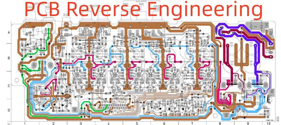
PCB reverse engineering is very important in different industries and is very popular for those utilizing PCBs in their daily tasks. When making use of PCB reverse engineering, you will be able to gain important information regarding their design and function, thereby allowing you to make repairs, produce less expensive alternatives to the competitors, as well as upgrade the older circuit boards.
Understanding ways in reversing the engineer PCBs, you will be able to have a full understanding of how a PCB will work as well as yield many benefits as a result.
What Does PCB Reverse Engineering Mean?
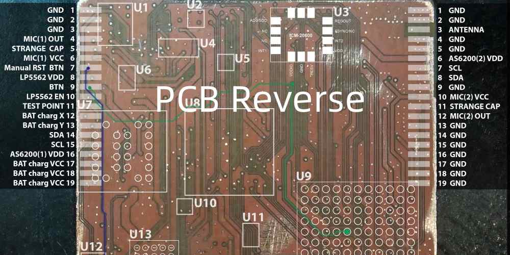
The process of PCB reverse engineering is a multi-layered one which features targeted reverse analysis, PCB research, as well as reproduction of the PCB design technology. This process is also useful for identifying and obtaining the design of the structural and functional characteristics of a product, coupled with the processing flow.
When a company uses this information they will be able to manufacture products having similar abilities and functions, although businesses would ensure that they aren’t manufacturing a complete replica of the reverse-engineered PCB.
Primarily, reverse engineering is used in determining and analyzing the principles of design behind a specific product. Out of all the methods for PCB reverse engineering, the most common has to do with the disassembling of the sample PCB and analyzing it. Using this analysis, the company will create documentation regarding the sample PCB that different team members will be able to review. Often, the documentation would include some information regarding the designing of the product, as well as the way it functions.
Companies may then utilize this information gathered from the ample PCB in manufacturing similar printed circuit boards, which may function more effectively compared to the offerings of their competitors. Asides from the ability of reverse engineering to assist companies in analyzing and outdo the products of competitors, it could also assist businesses in improving their PCB offerings. PCB reverse engineering for instance can assist them in enhancing the functionality of their boards through spotting poor designs, security issues, and obsolete parts.
Steps in PCB Reverse Engineering
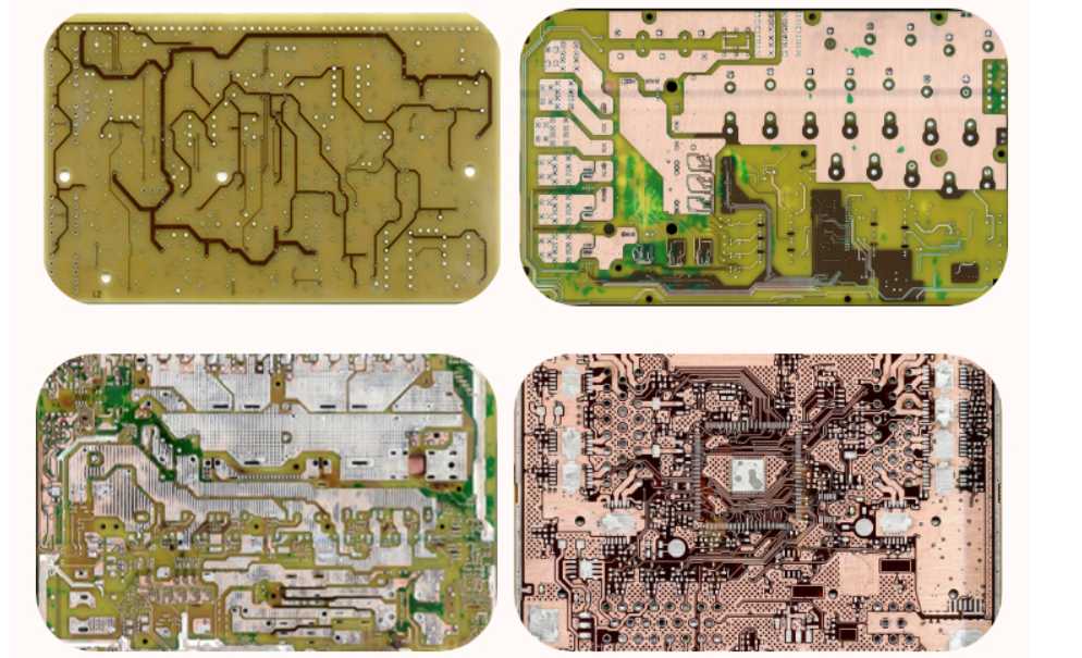
The process of PCB reverse engineering comprises steps that require careful attention. However, this process can be a very easy one if you take the necessary precautions.
PCB reverse engineering is best carried out by a professional. There are several stages of PCB reverse engineering. Some of which include making initial drawings and photographs of circuit boards which are uploaded to reverse engineering programs.
Immediately these boards are uploaded, you need to create the layout of the PCB and then use it to design schematics.
PCB Scanning for Image Prep
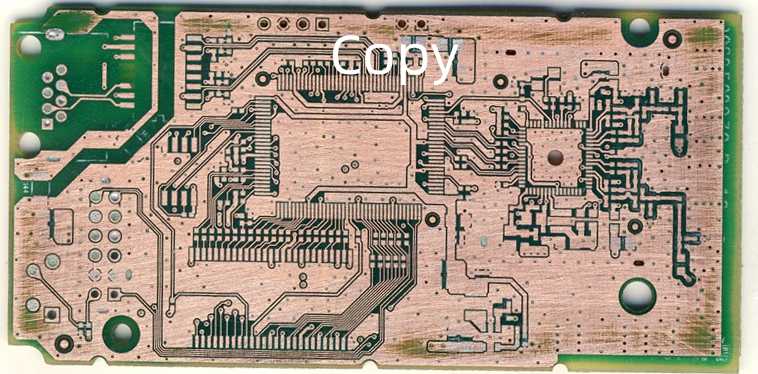
To start the process of PCB reverse engineering, you need to scan or take a picture of the board. If you prefer to take pictures of the board, capture both sides. Also, it is important to photograph the board on a dark background. This is because circuit boards usually have so many holes and you would want to avoid any other background showing through the holes. Dark backgrounds avoid confusion when it comes to the constitution of a board. In some cases, light backgrounds appear like copper.
You can make use of a high-quality camera to take a good photograph of the PCB. High-quality cameras like Smartphones or digital cameras are very detailed. Furthermore, the PCB must be well lit as this will enhance the image of the board. PCB Scanning or photographing requires you to carry out image editing or color switching.
Upload the Image
The next step is to upload the pictures you have taken to a reverse engineering software program. It is advisable to crop the image before uploading it. When you do this, the picture will only show the PCB. There are a lot of free online programs that can edit any picture and manipulate important features of a circuit board.
A good example of software to use is Inkscape or GIMP. These two software programs are free online graphics editors. You can as well use Dia for multi-purpose diagramming. Another program that can help you transform bitmap to vector graphics is AutoTrace. You can consider any of these programs for the layout creation and schematic development processes. However, you may still need CAD software once you have completed these processes.
Layout Construction
In this step, you will have to create a 3D layout of the circuit board. This reveals the electromagnetic field distribution of the system and how it is arranged. Also, the PCB layout shows other PCB parts like conductive elements and components that aren’t in the schematic.
You can scan the PCB drawing and upload to AutoTrace if the circuit board you are reverse engineering is a simple one. AutoTrace will easily convert the bitmap picture and then convert to a vector graphic. This helps to get the schematic of the board easily.
More complex boards usually require your image to go through several editing steps before creating a schematic. These steps will require some skills and also need more time.
Create Schematics
After you have constructed the layout, you need to design a schematic. When a circuit board schematic is designed, you will be able to view all of the PCB’s components.
The schematic diagram usually looks like a 2D CAD assembly drawing. With this, engineers can view how components connect differently and the functions of these components. These details are crucial when you are trying to reproduce a circuit board or make a repair. Programs like AutoTrace can help you with creating a schematic. Target 3001 is a PCB layout program that can be of help.
After the schematics have been created, the two sides of the board must be combined and the tracks must be arranged. Also, you will need to use symbols to label components. All these will make the interpretation of the schematic very easy.
Benefits of PCB Reverse Engineering
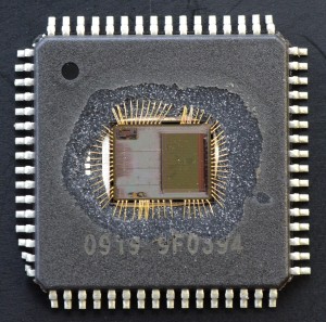
PCB reverse engineering offers a lot of benefits. You can produce a less expensive and more effective model of a PCB through reverse engineering.
Maintenance of crucial PCBs
In some scenarios, an outdated circuit board can carry out some necessary functions like powering an electronic component. It might be very difficult to replace or repair a faulty board. The best thing to do is reverse engineer the outdated board. This enables easy maintenance of crucial boards and as well the opportunity to clone these boards to function as replacements
Determine the weaknesses in other PCB designs
PCB manufacturers always look for ways to produce better boards than their competitors. Reverse engineering helps you to discover weaknesses in a competitor’s board. This information helps manufacturers to make some improvements to their boards. Discovering the weakness of a competitor’s board can help you create a board that serves unique purposes.
Get information on PCBs
The majority of contemporary circuit boards feature CAD data for review. Some PCBs have no available information about them. In such a case, PCB reverse engineering helps to collect data on a board. Furthermore, reverse engineering helps to generate documentation on a product. In the long run, this helps to reproduce or replace it.
Produce less costly PCBs
PCB Reverse engineering helps you to discover the exact amount it costs to manufacture a board that is being sold at a high price. Lack of competition makes a company sell their boards at high prices. It is possible to produce a similar board at a much cheaper price. New customers will want to explore your options.
Reduce dependence on experts
Most people usually end up contacting experts for repairs and troubleshooting problems when their PCBs become faulty. You might not have access to any experts that can handle your PCB well. This can put you on a bind. With PCB reverse engineering, you can get important information about a board and locate areas that cause problems. For this, you don’t need a professional’s help.
PCB Reverse Engineering has a lot of advantages which are very beneficial for both manufacturers and PCB users. With the information above, one can tell how important PCN reverse engineering is.
Best Providers of PCB Reverse Engineering Services
R & M TECH
For more than 15 years, R & M TECH have been involved in offering PCB reverse engineering services offering new boards coupled with the redesign of already-existing boards for customers to save money and time.
They make use of different technologies to scan the circuit boards, photos, or artworks, to help in manufacturing CAD data for the photo plotting for enabling the manufacturing of new printed circuit boards. To replace the board as well as save costs for redesigning CAD layouts, there is a more economical way. This also makes sure that the new printed circuit board would work just the same way as the original, while removing any errors.
RayMing
This PCB reverse engineering services provider is ranked the best in China. With more than ten years professional experience in engineering dealing in electronic hardware PCB reverse engineering, they have a team that can handle any task.
RayMing can assist you with PCB reverse engineering services, remanufacturing unsupported and obsolete electronic card assemblies and circuit boards. Rayming’s electronic reverse engineering involves determining how the manner in which the design of a specific item was made, as well as the way it functions so as to reproduce or remanufacture it from the PCB to its schematic.
Furthermore, this PCB reverse engineering supplier is focused on offering the best support to customers in the PCB copy and PCB clone industry.
Candor Industries
The creation of new technologies as well as designs requires great partnership, the process of production needs not just a great product, but communication support and knowledge. Candor engineering and sales team are usually set to assist and will give answers to queries promptly.
Furthermore, this PCB reverse engineering supplier has a great reputation and is one of the most trustworthy and reliable black OCB producers in the country. This reputation as built out of many decades of serious dedication to their customers as well as their never-falling promises to deliver customers circuit boards on time.
Whether you decide to order bare boards or choose a complete PCB solution, this PCB reverse engineering services provider is known to offer the best possible lead times without having to compromise on their service and quality.
Rush PCB
Rush PCB have revealed that many industries need PCB reverse engineering services to maintain electronic products, which are no longer available due to obsolescence as well as other reasons. Also, for PCB reverse engineering, make use of a 3D scanning technology like X-ray tomography, laser scanners, as well as a light source converter that is structured for the measurement of dimensions and then constructs the 3D visual models.
IAL
The multilayer PCB reverse engineering services are as varied and unique as customers that request for them. This PCB reverse engineering needs the utilization of deprocessing , cross-sectioning, as well as electron microscopy skills that this Company has been able to acquire since its establishment, and with years of experimentation and experience.
Whether you are seeking a simple SEM inspection or cross-section to determine some of the parameters of a process or a layer-by-layer full depressed sample that is set using high resolution electron and optical microscope images, which can be utilized to fully reverse engineer the PCB, this company can offer you the required data.
Furthermore, for the majority of PCB reverse engineering services, IAL has the ability to offer mosaic SME images of the large functional blocks and at very high magnifications. This could be stacked into the multilayer image with very precise alignment that allows the tracing of the signal over the device’s multiple layers.
Conclusion
In summary, the process of PCB reverse engineering services is a multi-layered one which features targeted reverse analysis, PCB research, as well as reproduction of the PCB design technology. This process is also useful for identifying and obtaining the design of the structural and functional characteristics of a product.
